Introduction
So this project came about because Wanita at ICStation was kind enough to send me some of their MAX7219 Dot Matrix Module Control Display DIY kits. These little 8×8 red LED matrix modules are super cute, and a steal at only $2.86 each!

8×8 red LED module from ICStation
I had 4 of the modules, so I took the code from my Pong Clock, stripped it down and created a mini clock. As well as the LED modules I used an Arduino to run code and a DS1307 clock module to keep time. If you want to make one yourself it’s not too hard – read on!
Mini LED Clock Features:
- Basic mode with large digits
- Slide mode where digits roll on and off screen
- Small digits with seconds mode
- Time written in words e.g. “Ten past Twelve”
- Date display
- 12/24 hour option
- Brightness option
- Random clock mode option that changes the display mode every few hours.
- Push button driven menus for setup & display selection.
Parts List
- 4 x MAX7219 Dot Matrix Module Control Display DIY kits.
- 1 x Arduino Uno or Duemilanove with 32k RAM.
- 1 x DS1307 real time clock module.
- 1 x Arduino prototyping shield
- 1 x breadboard for testing (optional)
- 2 x Push to make buttons such as these.
- 1 x A to B type USB Lead
- 1 x Mains to USB power adapter
- Wire
You’ll also need some tools:
- Fine tip soldering iron
- Solder
- Liquid solder flux
- Tweezers
- Wire cutters
- Magnifying glass – if you don’t like squinting at tiny components.
And the code itself:
Building the Matrix Kits
The kits use a red LED matrix which plugs into a PCB with onboard MAX controller chip. The chip takes all the hard work out of controlling the LEDs. You simply need a few wires to connect the module to an Arduino, then you can control it using software. The other cool thing is these matrix PCB’s clip together with plastic jumpers, so you can make displays as big as you like. The kits need to be soldered and uses surface mount components. I was a little nervous about building them at first – some of the resistors and capacitors were super tiny!

The parts in the kit
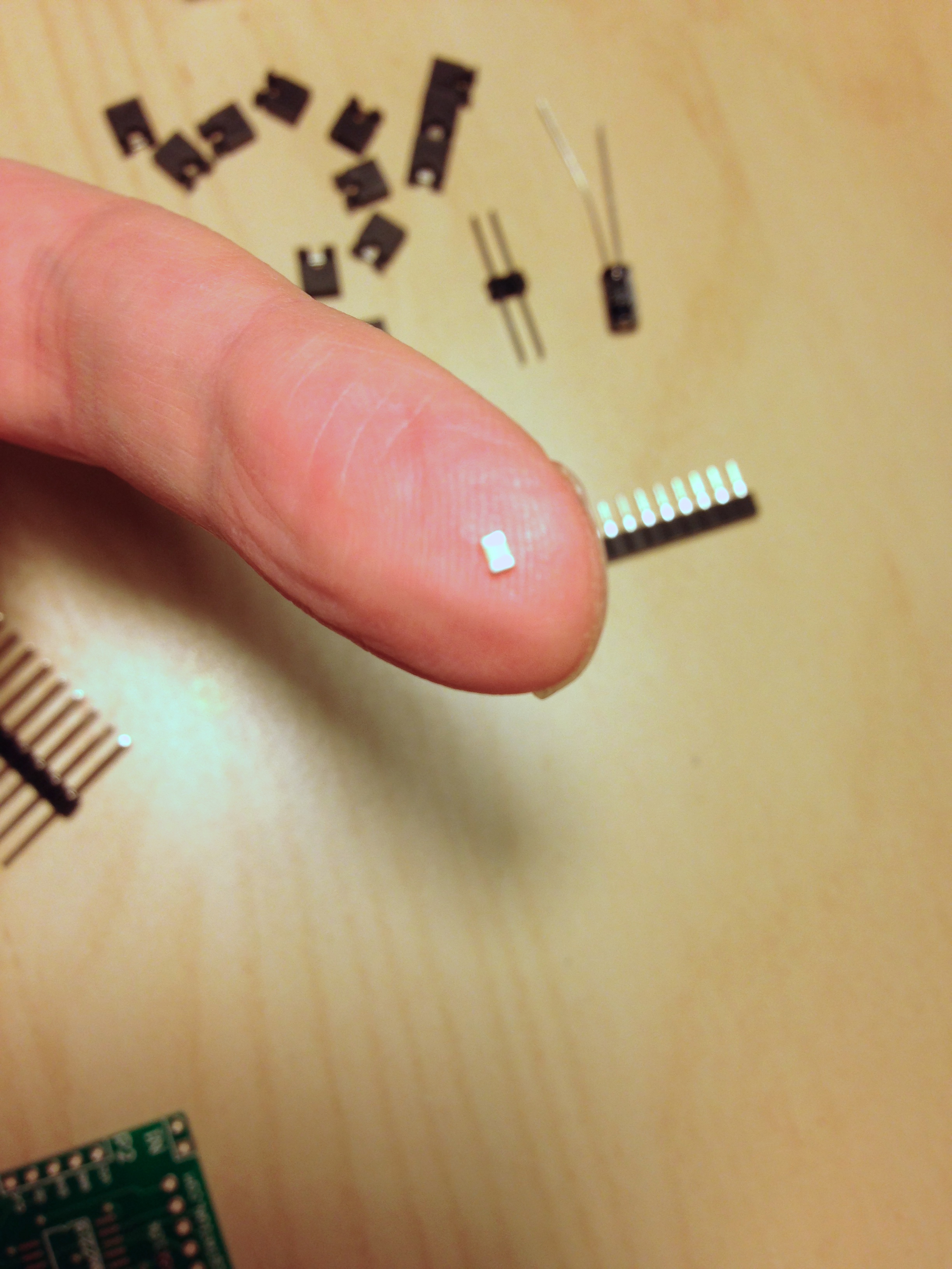
Teeny surface mount resistor

MAX surface mount LED Controller IC
Surface mount soldering wasn’t as hard as I thought. There are some useful surface mount soldering videos which, whilst not the most exciting thing to watch, really helped me get the hang of it. The secret sauce to it all is liquid solder flux. This makes the solder bond to both the component and the circuit board.

Tools I used – liquid solder flux, solder, and a fine top soldering iron.
Basically you wet the PCB metal pads with the flux, melt some solder on the iron, then whilst holding the component in place with your finger or tweezers, touch the iron to the joint and the solder flows onto it. It’s actually quite satisfying to do when you get the hang of it. I found using a breadboard was helpful to hold parts in place.

Handy breadboard
As for what components to solder where, you can work it out pretty easily from the ICStation website. One thing you need to be careful of is making sure you solder the pins that are used to connect different matrix modules together on at 90 degrees to the PCB. I did a few at a bit of an angle by mistake, and it meant the matrix modules didn’t clip together as well, so I had to go back and re do them.

Make sure the pins around the edge are at 90 degrees to the PCB, or the boards don’t clip together well.
Once each matrix was built, I tested it using the demo program available from the matrix product page on ICStation’s website. I’ve also put this program in the download with my clock code. It’s called “LEDDemoMatrix.pde” and can be found in the matrix_test/LCDemoMatrix folder. To use it, one matrix needs to be connected up as follows:
- Arduino Pin 10 to LOAD
- Arduino Pin 11 to CLK
- Arduino Pin 12 to DIN (Data In)
- Arduino 5v to 5v
- Arduino GND to GND
All being well your matrix should light up in various patterns to show it’s working.

The test program running

4 modules built – don’t look too closely at the surface mount soldering!
So as I said the clever thing about these modules is that they join together using little jumper connectors, so you can chain them together in a line to make bigger displays. We need all four in a line for our clock, so join them as in the picture below. Make sure all the matrices are facing the same way, so that you connect the DOUT (data out) pin from one to the DIN (data in) pin on the next.

Joining the modules together
OK let’s take a look at the other bits we need for the clock.
The Arduino
The Arduino microprocessor runs the clock software, plus provides inputs and outputs that we connect the matrix modules, buttons and clock module to. Ensure you get an Arduino with 32k RAM such as the The Arduino Uno. Older Arduino’s with 16k won’t have enough room to store the clock code.

Arduino – this one is an older 32k ‘Duemilanove’, the latest model is the Uno. Both will work fine.
The DS1307 module

DS1307 module
The DS1307 module contains a DS1307 chip that keeps time, along with a battery that runs the chip if the main power is disconnected. That way even if you unplug the clock, when you plug it back in the time will still be correct. It only needs 4 wires to work. 5v and GND for power, then SDA and SCL which are used to send clock data via the i2c protocol to the Arduino.
The Protoshield
The prototyping board or ‘shield’ plugs into the Arduino making it easy to add other components. It brings the Arduino’s input and output pins onto a circuit board we can solder things to. We’ll use this to mount the DS1307 module, plus to connect the matrix display connections and buttons to.

Protoshield
I can’t really give you detailed instructions for what to solder where on the protoshield, as different boards have different layouts. However it should be pretty easy to figure out when you look at the list of all the pin connections needed further down. Make sure your shield comes with header pins so you can plug it into the Arduino (they’re not shown in the picture above). Some shields also come with additional bits – often a reset button as they mask the one on the Arduino, and sometimes extra LED’s for you to use.
Buttons
You can use any push to make buttons. For example PCB mountable ones like below are good for soldering to the protoshield, or you could have some other type you connect via wires, say if you wanted to mount them in a case.

PCB mounting buttons
Power
For the power supply I used a 500 milliamp USB adapter like this one with an A-B type USB cable into the Arduino’s USB port.

USB Power supply

A to B type USB Lead
For testing I powered the clock with my Macbook, but be careful, if you have any shorts you could fry your computer’s USB ports!
Connecting it all up
Like I said, I can’t give you detailed instructions on what to solder where on the protoshield as they differ depending on what you buy, but below is a list of all the pins and what they need to connect to. Ideally try it out on a breadboard first to check it works, then move it to the protoshield.
Connecting the LED Matrix modules:
Once your 4 matrix modules are joined together in a line with the black jumper connectors as described earlier, look for the end one with the DIN (Data In) pin free. Connect the pins on that matrix as follows:
- Matrix LOAD to Arduino digital pin 10
- Matrix CLK to Arduino digital pin 11
- Matrix DIN to Arduino digital pin 12
- Matrix 5v to Arduino pin 5v
- Matrix GND to Arduino pin GND

I created a connector board that plugged into my matrix using some PCB stripboard and a 6 pin IDC socket. That way I could plug or unplug it from the Arduino.
Connecting the DS1307 module:
- SDA to Arduino analog pin 4
- SCL to Arduino analog pin 5
- 5v to Arduino pin 5v
- GND to Arduino pin GND

Here’s my DS1307 module with the 4 connectors. Green is SCL, yellow SDA. Red and black are +5v and GND.
Connecting the Buttons:
- Button 1 goes between Arduino digital pin 2 and GND
- Button 2 goes between Arduino digital pin 3 and GND

All the connections completed. The wires for the buttons go off top left. (Ignore the extra brown wire there – it was just for testing!)

Finished protoshield
My protoshield came with 2 LEDs and a reset button. I connected the green LED between 5v and GND to show power on. The red LED is connected between Arduino digital pin 13 an GND as the clock sketch flashes this to show it’s running. The reset button was already connected to the Arduino’s reset pins. You can also see the connections for the displays on the left (cable tied to the board), and the button connections top left.
Uploading the Clock Code
The last job is to upload the clock code to the Arduino. First you’ll need to download the Arduino programming software called the Arduino IDE. The current clock code was tested with IDE version 1.6.5. You can download the IDE from the Arduino site: http://arduino.cc/en/Main/Software
Once the IDE is installed download the Mini LED Clock code from my page on GitHub by clicking the “Download Zip” button bottom right. Unzip the file and inside you will see 3 folders:
- libraries – contains extra software code the clock needs to work
- matrix_test – this is the demo program ICStation provide to test the matrix kit is working as explained earlier.
- mini_clockx_x (where x is the version number) – this contains the main clock code.
Next job is to install the libraries. When you installed the Arduino software it should have created a folder somewhere for your sketches (projects) to go in. Inside that folder should be another folder called libraries. Open the libraries folder in the clock download and copy the 4 folders there into the libraries folder in your Arduino projects directory. The 4 libraries are called ‘Button’, ‘FontLEDClock’, ‘LedControl’ and ‘RTClib’.
Now quit and restart the Arduino IDE to make it pick up the new libraries. After restarting, go to the Sketch -> Import Library menu. If the libraries are in the right place you should see the 4 names listed in this menu.

Look for the 4 library names above to appear in this menu. (My menu has some extra libraries listed too that aren’t needed for this project)
If not, go back and check you have them in the right folder.
Now go to the File menu and open the main clock sketch – it’s in the mini_clock folder and is the file ending in .ino. You should see the code appear in the main window. Pick your Arduino board type in the Tools -> Board menu and hit the Verify (check mark) icon. This tests the code and should compete without errors. If you do get errors here, you’ve most likely not got the 4 libraries in the right place or you’re not using the correct version of the Arduino IDE software – make sure you are using 1.6.5 and not a newer version.
OK, time to upload the code to your Arduino. Plug the Arduino into your computer with the USB cable. Click upload and wait for the code to be uploaded. Watch the TX and RX LED’s on the Arduino flash for signs of data transfer. If you’ve got everything plugged in right the clock should spring to life. Now you can unplug it from your computer and use the USB power adapter. Use the buttons to set the time and then sit back and admire your handiwork.
And if you really, really like the project, here’s my bitcoin address! 1JPdDk4DiKYDsjTYghHatJp1FFQsv6bpEv


Troubleshooting
I get an error compiling:
- Check the libraries are installed in the correct folder and appear in the menu
- Make sure you have restarted the Arduino IDE after adding the libraries.
- Make sure you are using Arduino software version 1.6.5.
I get an error uploading to the Arduino:
- Check your board type and serial settings are correct in the Tools menu.
- Check your Arduino has 32K RAM or more.
The clock doesn’t change:
- Normally a wiring issue. Check the LED on Pin 13 of the Arduino flashes. If not then the clock chip is not being read. Check your connections to the DS1307.
- You must have a working battery on your DS1307 module for the clock to run.
The displays don’t light up / light up erratically.
- Check your wiring to the first matrix.
- Check all the jumper pins are pushed in on the other matrices.
- Try another power supply.
- Check each matrix with the Demo program as described earlier to make sure they are soldered correctly.
The text on the displays is rotated.
- This is most likely because you don’t have the exact matrix modules from IC Station. Other modules from eBay can be wired up differently, so the LED’s are in a different order. You can usually fix things by tinkering with the function “plot” in the code. Look for the comment “plot a point on the display” and the line starting “void plot”. Switch the x and y in the 2 lines that start ” lc.setLed(address, y, x, true ); and lc.setLed(address, y, x, false);”. This will plot the pixels 90 degrees around.
The text on the displays is garbled or out of order.
- This is most likely because you don’t have the exact matrix modules from IC Station. Other modules from eBay can be wired up differently, so the LED’s are in a different order. You can usually fix things by tinkering with the function “plot” in the code. Look for the comment “plot a point on the display” and the line starting “void plot”. If the text is our of order you can try changing the address=0 to address=3 lines around. These control which display is 0,1,2, and 3. If you swap the numbers around so they go from 3 to 0 this will invert everything. It’s worked for a few people!

Hey, I used your code to make this clock, but I’ve had no end of grief using the DS1307 adafruit library that you’re using here. It just doesn’t work properly with most of the Chinese TinyRTC modules. I’ve re-written your code to use the new default DS1307 and TIME libraries and all of the weirdness I’ve experienced with the RTC is gone. Also I’ve noticed that the matrix seems to draw faster as well (that might be subjective though). I’m working to expand the clock to use the Dallas temp sensor you can solder in to the Tiny RTC module and expand the matrix to 24×16 to display the extra information. Everything was going swimmingly except now when I try to read the temperature from the Dallas device the LED matrix freezes so I’ve got some work left. If you’re interested I can post the updated code to use the default Arduino DS1307 and Time libraries. I’ve found them to work 100% with the TinyRTC modules vs the adafruit DS1307 library.
Hey, what issues have you been seeing with the RTC modules? I’ve seen my clock lose accuracy.
Love to have the code with the new libraries if it’s functional – I can post on my page as an alternative.
When you say these are the new default libraries – where are they from?
Cheers
http://playground.arduino.cc/Code/Time
Just started playing with this today.
Has a twelve hour function that is very easy to use.
I think I mentioned it to you recently.
Kirby H
i made it, so beautiful
Hello,
thanks for the code for this great and nice clock!
I changed the RTC 1307 with RTC3231 and it works more precise.
Now, I’d like to add a DTH22 Sensor to show the temp and humidity … Someone have already done this mod ?
Thanks and Cheers
Enzo
Hey Enzo, I’m not sure if anyone has. You’d need to create a new function to get and display the temp – just copy one of the more simple functions like the one that prints the version to see how it works writing characters to the display, then have it call it when you press a button (like the date) / or every X seconds / mins.
Hello jjazzyj!
Managed to finish all your code?
I am interested, for goodness and kindness!
Thank you
Hi
“Greeting of the day”
When I am verifying the code, getting this msg. ………..
D:\MK\ELE\miniclock-master\miniclock-master\mini_clock1_0\mini_clock1_0.ino: In function ‘void switch_mode()’:
D:\MK\ELE\miniclock-master\miniclock-master\mini_clock1_0\mini_clock1_0.ino:1255:3: warning: deprecated conversion from string constant to ‘char*’ [-Wwrite-strings]
};
^
D:\MK\ELE\miniclock-master\miniclock-master\mini_clock1_0\mini_clock1_0.ino:1255:3: warning: deprecated conversion from string constant to ‘char*’ [-Wwrite-strings]
D:\MK\ELE\miniclock-master\miniclock-master\mini_clock1_0\mini_clock1_0.ino:1255:3: warning: deprecated conversion from string constant to ‘char*’ [-Wwrite-strings]
D:\MK\ELE\miniclock-master\miniclock-master\mini_clock1_0\mini_clock1_0.ino:1255:3: warning: deprecated conversion from string constant to ‘char*’ [-Wwrite-strings]
D:\MK\ELE\miniclock-master\miniclock-master\mini_clock1_0\mini_clock1_0.ino:1255:3: warning: deprecated conversion from string constant to ‘char*’ [-Wwrite-strings]
D:\MK\ELE\miniclock-master\miniclock-master\mini_clock1_0\mini_clock1_0.ino: In function ‘void setup_menu()’:
D:\MK\ELE\miniclock-master\miniclock-master\mini_clock1_0\mini_clock1_0.ino:1339:3: warning: deprecated conversion from string constant to ‘char*’ [-Wwrite-strings]
};
^
D:\MK\ELE\miniclock-master\miniclock-master\mini_clock1_0\mini_clock1_0.ino:1339:3: warning: deprecated conversion from string constant to ‘char*’ [-Wwrite-strings]
D:\MK\ELE\miniclock-master\miniclock-master\mini_clock1_0\mini_clock1_0.ino:1339:3: warning: deprecated conversion from string constant to ‘char*’ [-Wwrite-strings]
D:\MK\ELE\miniclock-master\miniclock-master\mini_clock1_0\mini_clock1_0.ino:1339:3: warning: deprecated conversion from string constant to ‘char*’ [-Wwrite-strings]
D:\MK\ELE\miniclock-master\miniclock-master\mini_clock1_0\mini_clock1_0.ino:1339:3: warning: deprecated conversion from string constant to ‘char*’ [-Wwrite-strings]
D:\MK\ELE\miniclock-master\miniclock-master\mini_clock1_0\mini_clock1_0.ino:1341:18: warning: deprecated conversion from string constant to ‘char*’ [-Wwrite-strings]
set_modes[1] = (“12 Hr”);
^
Sketch uses 14,100 bytes (43%) of program storage space. Maximum is 32,256 bytes.
Global variables use 1,203 bytes (58%) of dynamic memory, leaving 845 bytes for local variables. Maximum is 2,048 bytes.
Are you using the version of the arduino software specified in the blog?
Fantastic man! for me work fine with ds3231 module and arduino nano! it’s really precise with ds3231 ! thanks thanks thanks!!!!!!!! You are great!!!!
My friend how to use DS3231 in this clock can you please help me.
some time has gone since your comment.
I’ve build the pong-clock and simply replaced the DS1307 by the DS3231 (as I only have the DS3231 at home). Same pins used, same I2C-address, … No need to change the code (OK,I’ve removed the debug-output to serial as I don’t need it). So I believe it should be the same to replace DS1307 by DS3231 in this project, too (will try later – still waiting for the LED-matrix to arrive from china…).
I tried everything to run the clock. I changed two clock modules. But the clock is not running. Matrix check, version 1.o Hello are displaying. I can toggle the switch 1. But I cannot toggle the switch 2. led on pin 13 does not flash. What is that I am doing wrong ,
Please someone help to run the clock
Sudha
s_dandala@yahoo.com
Hard to say without looking but sounds like the clock chip not running somehow.
Download one of the many simple DS1307 demo sketches – i think some come with the library I use if you google it. And just see if that works. There is one that prints out the time to the serial display I used. Then you’ll see of the clock chip is ok.
It Looks like as someone mentioned the cheap DS3017 module does not work with the code in your project. I am going to try DS3132 module with Arduino Time code.
Sudha
Nick in your project you mentioned connect to DATAIN to end module. Do you mean Left end module ?
After connecting the 4 modules you should only have one module left with DataIN. That is the one you need to connect to. The other end will be DataOUT.
Nice project Nick. Thanks for sharing. I’m not able to set the time with Button 1 and Button 2. Clock is up and running well. Not able to understand “After connecting the 4 modules you should only have one module left with DataIN. That is the one you need to connect to. The other end will be DataOUT.” and not using the IC station MAX module. – Please help
Thanks in advance.
Thanks! Check you have the right pins on the arduino for the buttons. They should just work if you have the wiring right.
As for the modules, they should have an “in” and an “out” pin on each one. So when you have connected all 4, you will have one module with an “in”, say on the right, then one on the far left with an “out” connector. The arduino is sending data to the modules, so you need to connect the line out the arduino to the “in” on the matrix. You can leave the “out” disconnected.
Be aware if you don’t use the IC station modules, some are connected differently which means you might get the text rotated or flipped in some way
Hello jjazzyj
Can send me default DS1307 and TIME libraries .
Thank You
Sudha
Hello
RTC is not running eventhough I changed 3 DS3017 modules. I checked the circuit several times.
Initial displays comes as mentioned. But the clock is not running. On the serial monitor it sya RTC is not running. What else I need to do to run the clock. I checked with RTC test sketches it also saya RTC is not running.
Sudha
use arduino Leonardo sda and scl pin to ds1307 sda and scl pin. doesnt work with uno.
Now I got the clock ticking. How do set the correct time, day, year etc.,
There is an option in the menu
Thank You. It did work.
Good morning,
Have been having a lot of fun the mini clock built, except that the display rotated 90 degrees.
Now runs the clock of vertically instead of horizontally.
How do I change it.
Many thanks
Martin Saarberg.
From the Netherlands.
Hi Martin, I’ve no idea how you’ve done that! Could you post a picture?
Hi,
Got the display used picture 1
This side by side picture 2
The result is picture 3
Would have liked picture 4
Thanks
Martin
Hi Nick,
Have you seen the photos ?
The question is how can I the numbers on the display 90 degrees turn.
Would love to hear from you.
Thanks.
Regards
Martin.
Hey Martin, the photos don’t show up on my phone. I’ll need to check on my laptop tomorrow. Nick
Try this void plot (byte x, byte y, byte val) {
//select which matrix depending on the x coord
byte address;
if (x >= 0 && x = 8 && x = 16 && x = 24 && x <= 31) {
address = 3;
x = x – 24;
y = 7 – y;
}
if (val == 1) {
lc.setLed(address, x, y, true);
} else {
lc.setLed(address, x, y, false);
}
}
Hello Friend! First, thanks for the reply; My Matrix looks like the picture (attached); Is an FC-16 Module. Thank you
________________________________ De: Nick’s LED Projects Enviado: quarta-feira, 8 de julho de 2015 07:02 Para: meuviolino@hotmail.com Assunto: [New comment] Mini LED Clock
Bernhard commented: “Try this void plot (byte x, byte y, byte val) { //select which matrix depending on the x coord byte address; if (x >= 0 && x = 8 && x = 16 && x = 24 && x <= 31) { address = 3; x = x – 24; y ="
Thanks in advents
Martin
Hey Martin i don’t see the pictures on my website either. Can you try and post them again?
Oke,
Regards
Martin
Nicely done! It works perfectly for me — almost. My modules, however, run 0-3, right to left, the opposite direction of the ones in your video. Hardware connections are solid, and of course I’m using the data-in side. But I get seconds on the leftmost matrix in the chain (#3), hours in the first, rightmost (#0), tens minutes in #1 and minutes in #2. It’s a working clock all right, but a little disconcerting, and consistent in the startup screen and all modes. My coding skills haven’t let me find a workaround yet. Any suggestions would be appreciated. I can send a photo if that would help.
Found it in the morning after a cup of coffee. Pretty simple, thanks to your excellent documentation. Looking forward to the Pong clock build next. Thanks.
Hi Nick,
I’ve just finished building your little mini clock project and It worked first time. The display looks great and it has some nice options in the menu. I noticed that you had problems with creating a scroll option, did you ever have another look at it. Is it also possible to have a time option for the random mode or changing the code to alter the time it takes.
I’m now designing a case for it using Corel and 3mm acrylic. Keep up the good work its much appreciated.
Kevin.
Great that it worked first time! I did have a scroll option on another project but I never ported it over. I don’t really have much time at the moment to go back and look at it. The random one should be easy to change, just play around with the coiners in the loops and delay statements to change it. Love to see the case when it’s done.
Hello!
I went step by step and I’m finnaly finished with the clock. I got an issue. The third display is doing some weird things. Depends on what is on the screen, sometimes the frist, second, third and the forth row doesnt lit up. Every led works as I tested them. Can this problem occur if there are wires touching? meanwhile, in order to make your projet work I had to offset the displays by adding wires between the connectors and flip the display for 90 degresee for the text to display in the right order. I can send you pictures of my setup and i can even film my screen so you can see the problem. If you can give me your gmail adress I can send it.
Yeah sounds like a bad joint somewhere. Maybe try and re-flow the solder on the LED matrix board and check nothing is shorting out.
That’s strange you had to offset the displays, did you buy the same ones as in the example I posted or a different make? I know some other makes have the matrices wired different so they show at 90 degrees. You could also try and change it in the code to flip X and Y per matrix.
Nick
Already tried to do the flip in the code itself but it didnt worked at all. Doing that half the leds didnt worked for some reason. Maybe it’s because I’m not that good at coding.
http://www.ebay.co.uk/itm/131231437382?_trksid=p2057872.m2749.l2649&ssPageName=STRK%3AMEBIDX%3AIT
I bought 4 of these. And because I’m not carefull enought I shorted some wires and now the third display is dead and I already bought a new one :P
Maybe the solder melted the plastic around the connetor and shorted 2 wires and that’s why the display acted so weird. It’s funny how, when I turn the arduino on. Every LED turns on. When I’m in basic mode the forth column of the third display works ( Yes I did a typo before, I meant the 2nd, 3rd and the 4th column didnt worked well). Anyway, when I go to small mode the 4th column stops working and when I go to words mode, the 2nd,3rd and the 4th column stops working. AND this issue is only present on the third display, every other display works perfectly.
Now I need to wait 4 days for my new display to arrive and then I will be extra carefull to not short anything.
If the issue is not resolved with a new undamaged display than there is probably something wrong with the second display? I mean can a faulty MAX chip transmit wrong data to the next display?
hello nick, i have build your mini clock and it is great to see it works
there is one problem when i see the dat ( example 23rd ) the numer 3 is not right
the date numbers 1 to 9 are correct but when the numbers 10 to 31 some pixels are missing can you help me see what that problem is? regards from the netherlands
Hey, that’s very strange. Do those leds work at all? Is it just when the date is shown?
I doubt it’s something wring with the second display but you could swap the order around and see if the problem moves along with it. The fact the 4th display is OK seems like the data is getting transmitted OK. Let’s try a new display first and see.
As for the rotation, it’s most likely those displays you have are wired the other way around. You should be able to swap it in code. In the function called void plot, what happens if you swap x and y in the 2 lines that say:
lc.setLed(address, y, x, true);
and
lc.setLed(address, y, x, false);
i.e. make them…
lc.setLed(address, x, y true);
and
lc.setLed(address, x, y, false);
Hi,
i tried this, but the text is rotated and appears mirrored. do you have an idea to fix this?
thanks.
Hey, try swapping the x and y in the plot function – there are (I think) instructions in the thread for someone else. Let me know! Nick
Hi!
Today I recieved the replacement display and it works now. Somehow I managed to damage the MAX clip and then the matrix display. OH well :P
So… because I’m done with the your project I made some changes to the code itself. I translated every word to “Slovenian” language and it works and I fixed the text offset when displaying date eg. “29th”. I had to change the offset value from 8 to 9 in order for the display to display the number correct. When the value was set to 8 the last column in the number 9 was offscreen ( It didn’t transfered to the third display).
offset = 9; //offset to centre text if 4 chars
My next goal is to change all text display to be scrollable in order to display all characters. eg. (Sept > September “scrolling from right to left”).
PS: I tried to flip the x and y in the code and it didn’t worked well. Half of the characters were missing or missplaced. Maybe I did something wrong or the matrix displays are wired in another way.
Thanks for the help anyway :P I hope you will post some more awesome DIY projects.
Hey, great you figured it out – and cool there is now a Slovenian version out there! I’ve not noticed the offset problem – I’ll have a closer look – thanks for pointing it out, and thanks for building one!
Hi again!
I forgot to post the picture of my mini clock and how I did the 90* flip.
I think that looks pretty cool with those extra wires! Nice how you have built it so it stands up on a board too.
thank’s Nick
i want to upload photo, when i made it from pcb dual layer and dot matrix 8×8 2,3 inch. but i can,t do in this site
now going to design a 2.3-inch dot matrix 5×7 6 pcs in dual layer pcb
with arduino pro mini 5v, ds1307 i2c bus
These displays modules are sold on aliexpress and also on ebay?
It is difficult to buy in Brazil
thanks
hi
i have question. how can i turn right position this numbers.normaly as show 21:45:34 but all numbers 90 degree left position . i cant turn led matrix how can i with code. help me please. can you give me you mail address plase.
Hi, I have the same problem, I connected four modules together and they are displayed like the person above me said. I need them rotated 90 degrees to have the correct orientation for my modules to fit in an enclosure. Thanks for the code by the way, it works well either way aside from the issue I’m having.
Hi, guess you didn’t buy the ic station displays ? Yours are wired up
differently. If you are ok with
Coding you can try swapping the x and y in the draw function. Alternatively the other guy here retired the displays so they were a rotated round.
Hi,
I used kits like the ones you use but with the MAX chip in a DIP package (the ones you put in a socket). That means the chip is located on one side of the module, making it longer. I saw you use a package with a surface mounted chip, so you can orient it any way you like. Next time I’ll get those modules, for now I’ll try swapping x and y. Thanks for the response. :)
how to change 5×7 font to 6×8 font ?
because i modified fontledclock.h to 6×8 font, not working. still 7 rows in display.
any idea for this is ?
Not easy I’m afraid, lots of things in the main code would need to be changed. You’d have to work through each function.
ok, thanks for your attention.
unfortunately, there are only 7 8 row flaming row. it would be good if the 8 row lit up into a bold character
there is a bounce effect, if the power supply connect outlet adjacent to the switch.
you can try it
Great work I liked very much. I will make one for me.thanks for the all idea. but I have a little doubt can I use DS3231 clock module. If can use how to do. Please reply 😊
Awesome work! I have 8 of the led matrices so 64×8 leds, how can I display both the time and date at the same time? I’m not very experienced at programming, could you point me in the right direction?
Great you like the project, unfortunately showing both time and date is quite a major rework of the code if you are a beginner. You’d first need to adapt the driver functions to map pixels to a bigger display, then adjust all the routines to draw in the larger space. Not impossible but not trivial either!
Hey Nick, built the Pong clock sucessfully – but cannot find the code for this one – pops up a dropbox error… Any ideas?
Chris
Strange, that link works OK for me. Try this: https://www.dropbox.com/s/3x5h3jheev5ljm2/mini-clock1.0.zip?dl=0
All found and now working :-) Thanks
Great!
Hooray, I managed to make the font 6×8.
look it this : https://youtu.be/Mp_xlsuyIMc
Hey that’s awesome! Can you put in a mode where you can switch between the 2 fonts?!
plot (15 – offset, 2, 1); //top point
plot (16 – offset, 2, 0); //top point
plot (15 – offset, 5, 1); //bottom point
plot (16 – offset, 5, 0); //top point
count = 500;
if (count == 0) {
plot (15 – offset, 2, 0); //top point
plot (16 – offset, 2, 1); //top point
plot (15 – offset, 5, 0); //bottom point
plot (16 – offset, 5, 1); //top point
}
yellow dot matrix each 2,3 inch (6cm x 6cm)
but not work in slide mode
halo gan,
bisa dishare code nya gan ? taruh di gist.github.com atau di pastebin.com .
thanks
hi nick, thanks for your nice clock !!
it’s work perfectly, but strange with display. it should rotate 90 degree, but not problem. i added
y = 7 – y; at plot function, it’s works !!..
void plot (byte x, byte y, byte val) {
//select which matrix depending on the x coord
byte address;
// byte address;
if (x >= 0 && x = 8 && x = 16 && x = 24 && x <= 31) {
address = 3;
x = x - 24;
y = 7 - y;
}
if (val == 1) {
lc.setLed(address, x, y, true);
} else {
lc.setLed(address, x, y, false);
}
}
before:
after:
<img src="https://cloud.githubusercontent.com/assets/275259/11287953/2a6e9bc6-8f52-11e5-958a-7e12e4623413.jpg"
Hi, can you put here one more time the code change for 90 degree rotation? I’m looking for that solution and the image link that you posted is broken. I would be grateful for your response :)
Hi,
here: https://gist.github.com/deanet/36c956540f240567f428
results: https://cloud.githubusercontent.com/assets/275259/11287953/2a6e9bc6-8f52-11e5-958a-7e12e4623413.jpg
thank you,
hi nick, thanks for your nice clock !!
it’s work perfectly, but strange with display. it should rotate 90 degree, but not problem. i added
y = 7 – y; at plot function, it’s works !!..
void plot (byte x, byte y, byte val) {
//select which matrix depending on the x coord
byte address;
// byte address;
if (x >= 0 && x = 8 && x = 16 && x = 24 && x <= 31) {
address = 3;
x = x - 24;
y = 7 - y;
}
if (val == 1) {
lc.setLed(address, x, y, true);
} else {
lc.setLed(address, x, y, false);
}
}
before:
after:
Hi Nick,
thank’s for this code, it’s work perfectly !
but i have a probleme, i use a DS3221.
can you give me the code for use it and i don’t know i can set the right time and date.
thank’s for all
post from france
Laurent
it’s me again,
i found how to set the correct date and time, electrical probleme with the button !
sorry !
so i use the DS3221 and your original code for the DS1307 and it seems works,
but Time move in the time, minute by minute…what’s the problem ?
for the rotation probleme i could see in the differents comments, this code works:
Laurent
“je suis Paris”
—————————————————————————————————-
//plot a point on the display
void plot (byte x, byte y, byte val) {
//select which matrix depending on the x coord
byte address;
if (x >= 0 && x = 8 && x = 16 && x = 24 && x <= 31) {
address = 3;
x = x – 24;
y=7-y;
}
if (val == 1) {
lc.setLed(address, x, y, true);
} else {
lc.setLed(address, x, y, false);
}
}
Hey Laurent. Not sure what you mean here, can you explain more?
hi,
I would like to bulid this clock, but I always get an error message.Please help me. these are the messages:
——————————————————————————————————————-
C:\mini clock\mini_clock1_0\mini_clock1_0.ino: In function ‘void switch_mode()’:
C:\mini clock\mini_clock1_0\mini_clock1_0.ino:1224:3: warning: deprecated conversion from string constant to ‘char*’ [-Wwrite-strings]
};
^
C:\mini clock\mini_clock1_0\mini_clock1_0.ino:1224:3: warning: deprecated conversion from string constant to ‘char*’ [-Wwrite-strings]
C:\mini clock\mini_clock1_0\mini_clock1_0.ino:1224:3: warning: deprecated conversion from string constant to ‘char*’ [-Wwrite-strings]
C:\mini clock\mini_clock1_0\mini_clock1_0.ino:1224:3: warning: deprecated conversion from string constant to ‘char*’ [-Wwrite-strings]
C:\mini clock\mini_clock1_0\mini_clock1_0.ino:1224:3: warning: deprecated conversion from string constant to ‘char*’ [-Wwrite-strings]
C:\mini clock\mini_clock1_0\mini_clock1_0.ino: In function ‘void setup_menu()’:
C:\mini clock\mini_clock1_0\mini_clock1_0.ino:1307:45: warning: deprecated conversion from string constant to ‘char*’ [-Wwrite-strings]
“Rndom”, “24 Hr”,”Set”, “Brght”, “Exit”};
^
C:\mini clock\mini_clock1_0\mini_clock1_0.ino:1307:45: warning: deprecated conversion from string constant to ‘char*’ [-Wwrite-strings]
C:\mini clock\mini_clock1_0\mini_clock1_0.ino:1307:45: warning: deprecated conversion from string constant to ‘char*’ [-Wwrite-strings]
C:\mini clock\mini_clock1_0\mini_clock1_0.ino:1307:45: warning: deprecated conversion from string constant to ‘char*’ [-Wwrite-strings]
C:\mini clock\mini_clock1_0\mini_clock1_0.ino:1307:45: warning: deprecated conversion from string constant to ‘char*’ [-Wwrite-strings]
C:\mini clock\mini_clock1_0\mini_clock1_0.ino:1309:18: warning: deprecated conversion from string constant to ‘char*’ [-Wwrite-strings]
set_modes[1] = (“12 Hr”);
^
Sketch uses 15,826 bytes (49%) of program storage space. Maximum is 32,256 bytes.
Global variables use 1,248 bytes (60%) of dynamic memory, leaving 800 bytes for local variables. Maximum is 2,048 bytes.
——————————————————————————————————————
I dont have too much experience . Anyone know what should I do???
Thanks G
Hi, Are you using the Arduino software IDE version 1.6.5 like the instructions say?
Nick
hi,
I downloaded the latest 1.6.7 software from https://www.arduino.cc/en/Main/Software page. Is it a problem?
i tried with 1.6.5 and its working fine THANK YOU. Its really nice I love it thank u
Hello,
Could somebody please upload a code where the 90degree rotation is included. I cannot seem to get control of that problem. The cirrent code shows too much space between the modules. My modules have true hole parts and no SMD so the problem is the IC that prevents me from placing the LED modules close together. A fix would be fantastic!
Thanks!
try this: https://gist.github.com/deanet/36c956540f240567f428
results: https://cloud.githubusercontent.com/assets/275259/11287953/2a6e9bc6-8f52-11e5-958a-7e12e4623413.jpg
thx that saved me from roteting the display fysicly
Hi All,
I got it working with the github link and 1.6.6
Pongclock is next…. The panels are here.
Great!
Very nice , but I did bug .dotm matrix where numbers and letters left oblique . Help please.
Bonjour,
Pour ceux qui auraient commandés ces modules LED max7219 de chez G&C:
http://stores.ebay.fr/G-C-Supermarket-HK-Co-Ltd/_i.html?_nkw=max7219+matrix&submit=Rechercher&_sid=1090683909
Il faut modifier le code suivant:
//select which matrix depending on the x coord
byte address;
if (x >= 0 && x = 8 && x = 16 && x = 24 && x = 0 && x = 8 && x = 16 && x = 24 && x <= 31) {
address = 0;
x = x – 24;
}
Comme ça ils sont dans le bon sens!
Et aussi pour que la date soit bien affichée et non coupée.
offset = 8; //offset to centre text if 4 chars
vers:
offset = 10; //offset to centre text if 4 chars
A cet endroit:
//select which matrix depending on the x coord
byte address;
if (x >= 0 && x <= 7) {
address = 3;
changer les lignes
address = 0
address = 1
address = 2
address = 3
vers:
address = 3
address = 2
address = 1
address = 0
Very good and thank you very much!
I read and modify on proteus. This project is very good!
This project is very good. Thank you very much!
And “void scroll” is not working. Anyone modify and finish it?
It’s been quite a while since I built this mini LED clock and I have noticed something. After few days or up to 2 weeks after I uploaded the sketch to the arduino I noticed that the clock / timer is running ever so slightly faster than a normal clock would, so the mini LED clock gets unsynchronized and that bothers me enough that I need to fix it somehow.
Do you maybe got any clue what’s the cause of this problem? I’m assuming it’s the DS1307 that is causing the problem.
Hi, I’ve had a Ds1307 do similar, the click gained 5 minutes a day. I changed the IC and the crystal and it solved the issue. Maybe start just with a new crystal.
Did you bought the replacement parts from ebay or from a better shop who sell better quality timers?
Yes I went to a better quality shop – the first parts I got were cheap eBay ones
I just checked some posts on arduino forums and it seems that people prefer the DS3231 chip. Can I just replace it without messing a lot around the sketch code?
I think so, there were some other posts about doing that – have a search of the comments on this and pong clock.
I searched all around the web but I can’t seem to find how to readjust the sketch code to work with the DS3231 module. I saw a few comments on this site but all of them are about people asking the same question as me.
This is what I did:
– I replaced the DS1307 module with DS3231 module by connecting it the same way with the battery. So that is that
– The time is frozen on the clock when I power it up.
– The seconds are not shown
– The DS3231 module seems to be connected right because of the red LED being lit.
– reuploading the sketch again doesn’t fix the issue.
I don’t know where to begin solving this issue. It’s probably a small change that needs to be done but by looking at the size of the sketch I really don’t know where exactly to search.
P.S. The module started to work just by it self for some odd reason.
After it started working I recompiled and uploaded the sketch again. It works but the “ds1307.adjust(DateTime(__DATE__, __TIME__)); // sets the RTC to the date & time this sketch was compiled” part of the sketch doesn’t work with this module. So I had to manually set the date and the time. Now I need to test how it works. Will reply in a few days to see how well the clock is synced with the real time clock.
Oui, le DS3231 fonctionne bien avec ce code, il n’y a rien à changer par rapport au DS1307.
Pour moi environ 1 seconde de décalage par jour.
Scrolling message has low speed.Is there any way to increase the speed with analog input.
waiting for the reply.
you can see here: http://www.planetarduino.org/?cat=432
Hello,
Came across your site and was interested in your led mini clock, had some matrices laying around and build your clock, had to redo the fonts and digits since they showed up on the display mirrored and tilted 90 degrees, but enjoyed it and got it to work.
Here is my video.
Hello,
i have a problem…sometimes, one matrix freeze, or all the leds are illuminated.
when i shutdown the system, or unplug it, the clock leds works perfectly .
can you give me the code to reboot the system automaticaly at the same time all days. at midnight for example.
thank’s
post from france
Have no solution, but the following links might help with resetting an arduino by software:
http://playground.arduino.cc/Main/ArduinoReset
http://www.instructables.com/id/two-ways-to-reset-arduino-in-software/
hi bro , thank you so much by sharing your proyect , so awesome …the only think what needs is to watch temp and one kind of alarm, would be awesome..congratulations! :D
Thanks!
Glad you like it! There are a few people who’ve modded the code for alarm / temp etc – search thru the comments!
hi, Niks, slide effect and random clock setting is not running in my clock.
thanks for your coding..its a wonderful clock. please suggest me what should i need do for getting this 2 modes. and also i want for scrolling watch
Great project, I built mine just over 9 or so months ago and still working flawlessly, however I’d like to make a modification by adding 2 more LED matrix squares to the existing 4 to display the hours minutes and seconds (Small mode) in that rounded characters found in basic mode, only I’m not that great at coding and simply would not know where to begin, Thanks for sharing this great project.
Hey David, glad it’s still going. Adding 2 more matrix units will be quite involved, you’d need to alter quite a lot of the code. Not something that would be a quick explanation unfortunately.
hi nick. im trying to do one as well but i only have two matrices. do i have to change a lot in the code when i subtract the number of matrices?
Hi, yes you’d need to change a lot – not an easy task unfortunately
Hi,
i´m using the DS3132-RTC-Chip and the 4 8×8 Matrix-Displays. I downloaded the latest Version of IDE 1.6.8. I´m using your script, but i have a Problem to set the Time manualy.
There is a Problem in the Date-Display. If i set the Date to “…adjust(DateTime(2014, 1, 21, 3, 0, 0));” , the Display Shows “Sunday” “2 ST” “JANUARY”. The Line “ds1307.adjust(DateTime(__DATE__, __TIME__));” is not working. is this a known Problem?
What can i do?
Hi Nick, i will show you (my and your) project -> a led miniclock with a bmp180 temp/pressure sensor….
Links:


Great Project, thanks again…. ;-)
Hey that’s fantastic – great you created a custom board for it too.
hello..
can you share of the code ?
thank you,
The link is in the blog – under the section “Uploading the clock code”
Hi. Thanks. Nice project. Help me please. How to remove left null? 00:10 -> 0:10
Hi friend! I am getting the following: error: variable ‘mytinyfont’ must be const in order to be put into read-only section by means of ‘__attribute __ ((progmem))’
unsigned int PROGMEM mytinyfont [42] [3] = {
An answer, I would be grateful!
I think the arduino ide has changed which means the code no longer works. Make sure you are using the version of the arduino software listed in the readme file
my buttonA not function. buttonB funtion correctly. I have try swap it, but still doesn’t working.
Sounds like faulty wiring / button or some such.
already check my button condition, swap button and pin but still doesn’t working.
Hmm, very hard to say unfortunately without seeing the board. You could set the button to another pin at the to of the script and try that pin instead
Thanks Nick. Will check the wiring and update. I dont have rotation issue as I have uploaded the updated code.
Apologies for the delay Nick. Still facing problem with Button 1 and 2.(Doesn’t work).
Find below for your reference.
https://drive.google.com/drive/folders/0B1thZ3PTe7RuSm5IbU9jQ1FlRFE?usp=sharing
Similar issue was faced by Sudha as well and later it was fixed. – How did you fix it Sudha?
Thanks in advance.
Hi Nick,
Now the clock is up and running and able to setup through button A and B. – Thanks many for the wonderful project.
Glad to hear it!
Hi Nick & All,
I wanted to let you guys know that I was facing this issue where the clock was ticking randomly for the past two days. After checking step by step I understood that the USB power was the culprit due to which RTC was not running,
Connected power supply to Matrix display through separate adapter and connected USB supply to arduino and RTC after which clock started running properly.
Hope this will help.
Thanks Nick again for the excellent project.
Great project dude.. loving this project.. i faced same 90 degree rotation issue. might be this will help to me..
can i have more project like this? or any idea for encloser/housing for this 8X8 4 mertix clock?
hello,
try this: https://gist.github.com/deanet/36c956540f240567f428
Thanks i will try sure. want to more project like this.
thanks man really!!!
Pingback: Jam Digital Dot Matrix Arduino Uno – calesmart.com
hello I saw this and thought this is just what ive been looking for so I built it and its great aslong as I use a mirror and hold it upside down. any ideas the display is upside down and mirrored
and yes I’m using different LEDS
Hey, you just need to play around with the plot() function.
The program assumes a display where the top left corner LED is pixel 0,0. The bottom right is 31,7. The plot function takes pixel points in this coordinate range and translates them into which individual matrix to use and where to put them on that matrix.
If your display is upside down it means when it’s plotting y=0 your LED’s are wired so it’s actually putting it at y=7. To account for this you can use some simple maths to swap the numbers over (so a 7 becomes a 0 and a 0 becomes a 7). To do so try changing the 2 lines that plot y:
lc.setLed(address, y, x, true);
lc.setLed(address, y, x, false);
to:
lc.setLed(address, 7-y, x, true);
lc.setLed(address, 7-y, x, false);
I.e. so when it’s fed a 7 it becomes 7-7 = 0. When it’s fed a 0 it becomes 7-0=7. When it’s 5 it’s 7-5=2 and so on.
Let me know if that helps then we can tackle the mirror bit!
That is the solution. Thanks
Hi I have implemented same clock and seems good. I have made DS1307 circuit myself and implemented with ardunio mini pro.
Clock circuit is below which i have implemented exact same (expect 0.1. But this running very fast by 10-12 min per day. Can anyone please help me for fix this issue?
thanks in advance.
Video of this clock
Looks great! I like the case!
I had this same issue and it was the crystal. It was cheap from eBay. I got one from another supplier and it fixed it.
Dear Nick
Thanks for your reply.
Let me try after replace crystal.. let you know the result.
Now i have installed this clock on my living room :) thanks for your support.
i am in trouble since yesterday. yesterday i have observed my clock is running 10 min faster. i have perform sketch burning process for sync time again from PC. But this time date/time not syncing with PC time and CLOCK RUNNING THREE TIME FASTER like raise. i have performed all troubleshooting step what i can do. rechecked, wiring circuit, replace crystal DS1307 chip, battery, fixed crystal body with ground etc. even try different version of code also. On serial monitor i have found wrong date/time is printing and two different value of date/time showing like:
0:8:23 Date 31 (Wrong time and day)
165:166:342 Date 232 (Not able to understand what is this)
there is two problem i am facing.
1) Clock running three time faster. This case clock is not usable for me
2) Date/Time not syncing with PC time after burning sketch
You can check my video which are showing clock running very fast
Photo album:
https://photos.google.com/u/1/share/AF1QipMMUaFD0StJG9CDjFB55GEf2hR3gJ1Cuf7AW-CKZTWj9dGcsvQofFVZzz_l4hKULw?key=eFNpbkVKNTZPcDYxZGNFZHk5OHo4NUN3ZlU2X3F3
Please help… Thank you so much in advance
Hey, sorry to hear you are having so many problems. I doubt it’s anything to do with the code as it’s working for other people but what you could do is search online for a basic sketch that reads the time from the ds1307. There should be some very simple examples you can upload just to check the time is OK. Maybe run it for a day printing to the serial console and then you can see if the basic hardware is OK.
Thanks
i have performed below action:
1) Changed crystal
2) Make ground to crystal and given more space on PCB for paste horizontally
3) Added some glue to crystal for paste in PCB
4) Added more wire for shorten path to battery ground
5) I was doing mistake while time sync that keeping power off to DS1307 circuit while sketch uploading to Ardunio mini by FTDI uploaded. After power on DS1307 circuit while sketch uploading now time sync properly with PC.
6) Added 22pf bypass caps to crystal legs.
Now clock working but still it’s 2 min delay on 10 hrs.
Seems good progress.. Still finding the way for fixed this issue as well.. :)
Definitely sounds like good progress so far! A few people have tried other clock chips – if you search DS in the thread for this and the pong clock you should find their posts.
Thanks.. Let me check
Hi Nick,
thanks for your nice Clock, i replaced the DS 1307 with the DS3213 without any problems
and also i made a PCB.
Nick Hello good day. I thank you for presenting your project. I made the clock and mel result was very good, but I want to ask why the set in 12 Hr mode and adjust the brightness to minimum and if disconnected from the source, the restart takes intermediate brightness and time 24 Hr ?, it is what I set unconfigures :(
Also after setting the date, day always appears independent of the current day d ela week Sunday.
Thank you very much for the help.
Sincerely,
Regards!!!
So just to be clear this code takes into account leap years?!
Hola gauravsanu, muchas gracias por tu ayuda, me sirvió bastante, ahora estoy feliz con mi reloj :)
Nice.. ;)
The brightness and 12/24hr are not stored when the clock is powered off. So the clock goes back to the default settings. If you want to change the defaults, look at the top of the code under where is says //global variables.
For example it says:
bool ampm = 0; // Define 12 or 24 hour time. 0 = 24 hour. 1 = 12 hour
If you set
bool ampm = 1; and upload the code. Then the default will always be 12hr.
Hope that helps!
I don’t understand what you mean about the date :(
Nick
Hi Nick, I have served much your help and have clarified my concerns.
Sure enough for my case simply initialize variables in the time mode and brightness that I always need. Excuse my ignorance, I am a rookie.
Here is my final product … https://drive.google.com/file/d/0B05JwBpCj_UiV1BYNWJmNVFtdnM/view?usp=sharing
Thank you very much!!!
Hey looks great!
Hi Nick!
You look strange to me or I do not understand! (easier!)
In the post you show the display module with the drive MAX7219 from the ICStation and the library shows the drive ht1632c; Are not different drivers? Could you explain this to me?
Thank you
The pong clock uses the HT1632, the mini clock (which I think you are posting about_ uses the Max chip. Hope that makes sense!
Sorry Nick! I’m wrong!
No problem!
Hi Nick,
i have some more concern:
1) Can i have more improved version of this with any additional feature?
2) I made some changes on code for display date in every 2 minutes. But on some mode it’s creating problem.. tried very hard to fix but still not able to solve.
3) I have added hourly alarm work fine..
4) Added remote control feature but on setting and word mode irremote not returns any value..
for display calendar and hourly buzzer:
void get_time()
{
DateTime now = ds1307.now();
rtc[6] = now.year();
rtc[5] = now.month();
rtc[4] = now.day();
rtc[3] = dayOfWeek(rtc[6],rtc[5],rtc[4]);
rtc[2] = now.hour();
rtc[1] = now.minute();
rtc[0] = now.second();
playHourBuzzer(); // Check time and play hourly buzzer
showCalenderInInterval(); // Show calendar
}
void showCalenderInInterval(){ //
if(rtc[1] != 0 && (rtc[1]%2) == 0 && rtc[0] == 59 && showingCalender == 0 ){
showingCalender == 1;
display_date();
showingCalender == 0;
return;
}
}
void playHourBuzzer() {
if(rtc[0] == 2 && rtc[1] == 0 && buzzerPlaying == 0 && rtc[2] >= 7 && rtc[2] <= 22) { // if 00 min and seconds
buzzerPlaying = 1 ;
playBuzzer(rtc[2]);
buzzerPlaying = 0 ;
return;
}
}
void playBuzzer( int numberofTimes ){
for(int b = 1; b <= numberofTimes; b ++ ) {
analogWrite(buzzer, 20);
delay(500); // …for 1 sec
analogWrite(buzzer, 0);
delay(500); // …for 1 sec
}
}
for Remote added this code to under run_mode() while loop after buttonA.uniquePress and buttonB.uniquePress:
it's work small_mode, basic_mode , slide and display setup menu, did't not working with word_clock and enter after set_intensity option. like set brightness, set time, date etc.
if (irrecv.decode(&results)) {
//Serial.print("Remote button pressed DEC ");
//Serial.println(results.value, DEC);
//Serial.print("Remote button pressed without changes ");
//Serial.println(results.value);
if( String(results.value, DEC) == "16187647" ) {
//Serial.println("A button pressed");
results.value = 0;
irrecv.resume(); // Receive the next value
switch_mode();
return;
}
if( String(results.value, DEC) == "16220287" ) {
//Serial.println("B button pressed");
results.value = 0;
irrecv.resume(); // Receive the next value
display_date();
return;
}
irrecv.resume(); // Receive the next value
}
even i have commented button_press check in brightness setting but irrecv results.value is blank in every time.
void set_intensity() {
cls();
byte i = 0;
char text[7] = "Bright";
while(text[i]) {
puttinychar((i*4)+4, 0, text[i]);
i++;
}
if (1 || irrecv.decode(&results)) {
while (String(results.value, DEC) != "16187647") {
Serial.println("!A");// button not yet pressed under set_intensity mode");
//Serial.println(String(results.value, DEC));
levelbar (0,6,(intensity*2)+2,2); //display the intensity level as a bar
while (String(results.value, DEC) == "16220287") {
Serial.println("B");
if(intensity == 15) {
intensity = 0;
cls ();
}
else {
intensity++;
}
//print the new value
i = 0;
while(text[i]) {
puttinychar((i*4)+4, 0, text[i]);
i++;
}
//display the intensity level as a bar
levelbar (0,6,(intensity*2)+2,2);
//change the brightness setting on the displays
for (byte address = 0; address < 4; address++) {
lc.setIntensity(address, intensity);
}
delay(150);
irrecv.resume();
}
delay(10);
irrecv.resume();
} // End of remote handler
//irrecv.resume(); // Receive the next value
}
/* Comment code of buttonA.uniquePress() and buttonB.uniquePress() */
}
Complete code is here
https://goo.gl/aL9IO0
Hey, great that you are adding to the code. Unfortunately I don’t really have time right now to debug your code, but hopefully you’ll get it working!
Hi gauravsanu.
Were you able to adapt the sketch with the IR Remote Control?
If you did, could you share it?
Hugs from Brazil
Hi Nick,
I was faszinated about your clock, so I’ve build my own “Digi-Clock”.
I’ve made some modifications/additions to your code and added a DS18B20 temp-sensor.
Finally there are now 6 different modes of displaying the time.
My word-clock mode is in German, so for an englisch version this part of code must be “reengineerd” ;-) or replaced by your code.
Take a look at my German site, where I added some fotos and a video:
http://www.arduino.joergeli.de/digiclock/digiclock.php
http://www.arduino.joergeli.de/digiclock/digiclock.php
I try ta add a direct link to the video here:
Greetings from Germany
Jörg
P.S.
The code and libraries are downloadable at the bottom of my page.
Wonderful joergeli,
I will try soon..
Good luck!
I would recommend to use the (old) libraries that I have added at the bottom of my page, because meanwhile some of the libraries are updated by the authors and with the new versions the compiling of the code runs in error.
Hey, this is really great! I love the extra modes like slide and temp. The second dots are also a great use of the other led’s on the display. Nice case too!
Hi Jorg, Nick
Implemented this clock and added hourly alarm (alert) feature..
Please have a look..
Thanks in advance
Hey nice mod!
Hello gauravsanu,
Congratulations!
It seems, there is still a little (timing?) problem with the temperature after alert has sounded?
AFAIK “-127 degees” means: no temp-data received.
Hi joergeli
After implementation temperate was showing only this error every time. But whenever i plug into laptop by FTDI header it’s not showing. I have added some extra wires for ground but still sometimes getting this error. but most of case it’s working properly.
I made it by adding 2 digits max 7219 Matrixx module and plans to add a digital chess clock mode,
Please help me and thanks very much.
/***********************************************************************
Mini Clock v1.0, Jul 2014 by Nick Hall
Distributed under the terms of the GPL.
For help on how to build the clock see my blog:
***********************************************************************
Modified to “Multi-Mode Digi Uhr” by joergeli
http://arduino.joergeli.de
Tested with Arduino-IDE v1.6.7
Modifications and differences to the original:
Using generic MAX72xx Matrixes (therefore chars are rotated 90 degrees!)
Using DS3231 RTC-Module (temperature-compensated = more accurate than DS1307)
Using Arduino-Nano V3.0
Translated daynames, monthnames, etc. to German
Added some “wipe”-effects
Added SmallSlide-Mode
Added Shift-Mode
Added automatic switching approx. every 2 minutes between Small-, Wordclock-, SmallSlide-, Slide- and Shift-mode. (Only when in circle-mode!)
(No automatic-switching in Basic-Mode!)
Added automatic displaying of dayname, date, month-name, year and week of year ( when second is 35 )
Modified buttonB as Toggle-Button, which toggles between “Display Date = On” and “Display Date = Off”
Added automatic Daylight Saving Time (+/- 1 hour)
Reprogrammed code of Wordclock-Mode to look like this: http://arduino.joergeli.de/wordclock/wordclock.php
(shows German-time in steps of 5 minutes, bottom-line shows +1, +2, +3, +4 minutes )
Added DS18B20 Temp-Sensor and displaying it’s temperature while in circle-mode when automatic changing of clock-mode occurs (approx. every 2 minutes).
Added Photoresistor (LDR) for automatic changing brightness (therefore brightness-menu removed)
***********************************************************************
Modified to “6 Digit Clock n Chess Clock” by syahr
email: syahr_monake@yahoo.co.uk
Tested with Arduino-IDE v1.6.5
Modifications:
Using 6 pcs MAX72xx Matrixes
Deleted SmallSlide-Mode, Shift-Mode, Word Mode, DS18B20 Temp-Sensor, Photoresistor (LDR)
Using DS3231 RTC-Module (temperature-compensated = more accurate than DS1307)
Plann : >>>> Added Chess Clock, please help ????
(Need Additional 4 pcs push button & Buzer)
1 pc Push for Pause, 1 pc Push for Player 1, 1 pc Push for Player 2, 1 pc Push for reset
I’ve made a digital chess clock using seven segment module, by benhur.goncalves
http://www.instructables.com/id/Arduino-Chess-Clock-Multi-game-Box/
***********************************************************************/
//include libraries:
#include “LedControl.h” // For assigning LED’s
#include // Font library
#include // DS1307 clock
#include “RTClib.h” // DS1307 clock, works also with DS3231 clock
#include // Button library by Alexander Brevig
#include // This library allows you to communicate with I2C
//define constants
#define NUM_DISPLAY_MODES 3 // Number of clock-modes (counting zero as the first mode)
#define NUM_SETTINGS_MODES 3 // Number of settings modes = 3 (conting zero as the first mode)
#define SLIDE_DELAY 10 // The time in milliseconds for the slide effect per character in slide mode. Make this higher for a slower effect
#define cls clear_display // Clear display
//sets the 3 pins as 12, 11 & 10 and then sets 4 displays (max is 8 displays)
LedControl lc = LedControl(11, 13, 10, 6);
//global variables
bool debug = true; // For debugging only, starts serial output (true/false)
bool show_intro = true; // Show intro at startup ? (true/false)
byte intensity = 7; // Startup intensity/brightness (0-15)
bool ampm = false; // Define 12 or 24 hour time. false = 24 hour. true = 12 hour
bool show_date = true; // Show date? – Display date approx. every 2 minutes (default = true)
bool circle = false; // Define circle mode – changes the clock-mode approx. every 2 minutes. Default = true (on)
byte clock_mode = 1; // Default clock mode.
// clock_mode 0 = basic mode
// clock_mode 1 = secon mode
// clock_mode 2 = slide mode
// clock_mode 3 = chess clock mode
////________________________________________________________________________________________
//Please don’t change the following variables:
byte old_mode = clock_mode; // Stores the previous clock mode, so if we go to date or whatever, we know what mode to go back.
short DN; // Returns the number of day in the year
short WN; // Returns the number of the week in the year
bool date_state = true; // Holds state of displaying date
int devices, dev; // Number of LED Matrix-Displays (dev = devices-1)
int rtc[7]; // Array that holds complete real time clock output
//char tempi[4]; // Holds temperature-chars for displaying temp
char dig[7]; // Holds time-chars for shift-mode
char shiftChar[8]; // Holds chars to display in shift-mode
////________________________________________________________________________________________
//day array (The DS1307/DS3231 outputs 1-7 values for day of week)
char days[7][4] = {
“Son”, “Mon”, “Die”, “Mit”, “Don”, “Fre”, “Sam”
};
char daysfull[7][4] = {
///”Sonntag”, “Montag”, “Dienstag”, “Mittwoch”, “Donnerst”, “Freitag”, “Samstag”
“Sun”, “Mon”, “Tue”, “Wed”, “Thu”, “Fri”, “Sat”
};
char suffix[1] = {‘.’}; //date suffix “.” , used in slide, basic and jumble modes – e.g. date = 25.
//suffix in German is always “.”
RTC_DS1307 ds1307; // Create RTC object – works also with DS3231
Button buttonA = Button(2, BUTTON_PULLUP); // Setup button A (using button library)
Button buttonB = Button(3, BUTTON_PULLUP); // Setup button B (using button library)
////////////////////////////////////////////////////////////////////////////////////////
void setup() {
digitalWrite(2, HIGH); // turn on pullup resistor for button on pin 2
digitalWrite(3, HIGH); // turn on pullup resistor for button on pin 3
if(debug){
Serial.begin(9600); //start serial
Serial.println(“Debugging activated … “);
}
//initialize the 4 matrix panels
//we have already set the number of devices when we created the LedControl
devices = lc.getDeviceCount();
dev = devices-1;
//we have to init all devices in a loop
for (int address = 0; address = 0 && x = 8 && x = 16 && x = 24 && x = 24 && x = 24 && x <= 47) {
address = 5;
x = x – 40;
}
if (val == 1) {
lc.setLed(address, x, y, true);
} else {
lc.setLed(address, x, y, false);
}
}
////////////////////////////////////////////////////////////////////////////////////////
//clear screen
void clear_display() {
for (byte address = 0; address < 6; address++) {
lc.clearDisplay(address);
}
}
////////////////////////////////////////////////////////////////////////////////////////
//intro: show intro at startup
void intro() {
for (byte address = 0; address < 4; address++) {
lc.setIntensity(address, 3);
}
for(int i=0; i<2; i++){
wipeBottom();
wipeTop();
}
wipeOutside();
char ver_a[12] = " Joergeli ";
char ver_b[12] = "Nicks Led";
for (byte address = 0; address = ‘A’ && c = ‘a’ && c = ‘0’ && c ‘) {
c = 44; // selector-arrow
}
else if (c == ‘~’) {
c = 45; // Ü
}
else if (c == ‘*’) {
c = 46; // Ö
}
for (byte col = 0; col < 3; col++) {
dots = pgm_read_byte_near(&mytinyfont[c][col]);
for (char row = 0; row > row))
plot(x + col, y + row, 1);
else
plot(x + col, y + row, 0);
}
}
}
////////////////////////////////////////////////////////////////////////////////////////
//putnormalchar:
//Copy a 5×7 character glyph from the myfont data structure to display memory
void putnormalchar(byte x, byte y, char c){
byte dots;
if (c >= ‘A’ && c = ‘a’ && c = ‘0’ && c ‘) {
c = 30; // clock_mode selector arrow
}
else if (c == ‘=’) {
c = 79; // equal sign
}
else if (c >= -80 && c <= -67) {
c *= -1;
}
for (char col = 0; col < 5; col++) {
dots = pgm_read_byte_near(&myfont[c][col]);
for (char row = 0; row = 0) && (x = 0) && (y > row)) { // only 7 rows.
plot(x + col, y + row, 1);
} else {
plot(x + col, y + row, 0);
}
//}
}
}
}
////////////////////////////////////////////////////////////////////////////////////////
// secon(=mode 1): show the time in small 3×5 characters with seconds-dots at bottom-line
void secon() {
char textchar[8]; // the 16 characters on the display
byte mins = 100; //mins
byte secs = rtc[0]; //seconds
byte old_secs = secs; //holds old seconds value – from last time seconds were updated o display – used to check if seconds have changed
cls();
//run clock main loop as long as run_mode returns true
while (run_mode()) {
get_time();
secs = rtc[0];
//check for button presses
if (buttonA.uniquePress()) { switch_mode(); return; }
if (buttonB.uniquePress()) { toggleDateState(); delay(1000); return; }
// when in circle mode and minute=even and second=14, switch to word_clock (mode 4)
if(circle){
if(rtc[1] % 2 == 0 && rtc[0]==14){
wipeInside();
clock_mode =4; // switch to wordclock mode
return;
}
}
//if secs changed then update them on the display
if (secs != old_secs) {
//bottomleds(secs); // plot seconds-dots at bottomline
// display date, when second=40 and date_state = true
if(rtc[0]==40 && date_state){
display_date();
return;
}
char buffer[3];
itoa(secs, buffer, 10);
//fix – as otherwise if num has leading zero, e.g. “03” secs, itoa coverts this to chars with space “3 “.
if (secs 12) {
hours = hours – ampm * 12;
}
if (hours < 1) {
hours = hours + ampm * 12;
}
//byte dow = rtc[3]; // the DS1307/DS3231 outputs 0 – 6 where 0 = Sunday0 – 6 where 0 = Sunday.
//byte date = rtc[4];
//set characters
char buffer[3];
itoa(hours, buffer, 10);
//fix – as otherwise if num has leading zero, e.g. "03" hours, itoa coverts this to chars with space "3 ".
if (hours < 10) {
buffer[1] = buffer[0];
//if we are in 12 hour mode blank the leading zero.
if (ampm) {
buffer[0] = ' ';
}
else {
buffer[0] = '0';
}
}
//set hours chars
textchar[0] = buffer[0];
textchar[1] = buffer[1];
textchar[2] = ':';
itoa (mins, buffer, 10);
if (mins < 10) {
buffer[1] = buffer[0];
buffer[0] = '0';
}
//set mins characters
textchar[3] = buffer[0];
textchar[4] = buffer[1];
//do seconds
textchar[5] = ':';
buffer[3];
secs = rtc[0];
itoa(secs, buffer, 10);
//fix – as otherwise if num has leading zero, e.g. "03" secs, itoa coverts this to chars with space "3 ".
if (secs < 10) {
buffer[1] = buffer[0];
buffer[0] = '0';
}
//set seconds
textchar[6] = buffer[0];
textchar[7] = buffer[1];
byte x = 0;
byte y = 0;
//print each char
for (byte x = 0; x 1:00am in 12 hour mode.
//do 12/24 hour conversion if ampm set to 1
byte hours = rtc[2];
if (hours > 12) {
hours = hours – ampm * 12;
}
if (hours < 1) {
hours = hours + ampm * 12;
}
//do offset conversion
if (ampm && hours 12) { hours = hours – ampm * 12; }
if (hours < 1) { hours = hours + ampm * 12; }
itoa(hours, buffer, 10);
//if hours < 10 the num e.g. "3" hours, itoa coverts this to chars with space "3 " which we dont want
if (hours < 10) {
buffer[1] = buffer[0];
buffer[0] = '0';
}
//print hours
//if we in 12 hour mode and hours < 10, then don't print the leading zero, and set the offset so we centre the display with 3 digits.
if (ampm && hours < 10) {
offset = 2;
//if the time is 1:00am clear the entire display as the offset changes at this time and we need to blank out the old 12:59
if ((hours == 1 && mins == 0) ) {
cls();
}
}
else {
//else no offset and print hours tens digit
offset = 0;
//if the time is 10:00am clear the entire display as the offset changes at this time and we need to blank out the old 9:59
if (hours == 10 && mins == 0) {
cls();
}
putnormalchar(9, 0, buffer[0]);
}
//print hours ones digit
putnormalchar(15 – offset, 0, buffer[1]);
//print mins
//add leading zero if mins < 10
itoa (mins, buffer, 10);
if (mins 12) { hours = hours – ampm * 12; }
if (hours < 1) { hours = hours + ampm * 12; }
//split all date and time into individual digits – stick in digits_new array
//rtc[0] = secs //array pos and digit stored
digits_new[0] = (rtc[0]%10); //0 – secs ones
digits_new[1] = ((rtc[0]/10)%10); //1 – secs tens
//rtc[1] = mins
digits_new[2] = (rtc[1] % 10); //2 – mins ones
digits_new[3] = ((rtc[1] / 10) % 10); //3 – mins tens
//rtc[2] = hours
digits_new[4] = (hours % 10); //4 – hour ones
digits_new[5] = ((hours / 10) % 10); //5 – hour tens
//rtc[4] = date
//digits_new[6] = (rtc[4]%10); //6 – date ones
//digits_new[7] = ((rtc[4]/10)%10); //7 – date tens
//draw initial screen of all chars. After this we just draw the changes.
//compare digits 0 to 3 (mins and hours)
for (byte i = 0; i <= 5; i++) {
//see if digit has changed…
if (digits_old[i] != digits_new[i]) {
//run 9 step animation sequence for each in turn
for (byte seq = 0; seq <= 8 ; seq++) {
//convert digit to string
itoa(digits_old[i], old_char, 10);
itoa(digits_new[i], new_char, 10);
//if set to 12 hour mode and we're on digit 2 (hours tens mode) then check to see if this is a zero. If it is, blank it instead so we get 2.00pm not 02.00pm
if (ampm && i == 5) {
if (digits_new[5] == 0) {
new_char[0] = ' ';
}
if (digits_old[5] == 0) {
old_char[0] = ' ';
}
}
//draw the animation frame for each digit
slideanim(digits_x_pos[i], 0, seq, old_char[0], new_char[0]);
delay(SLIDE_DELAY);
}
}
}
//save digita array tol old for comparison next loop
for (byte i = 0; i <= 5; i++) {
digits_old[i] = digits_new[i];
}
}// end of secs/oldsecs
}// end of while run_mode
}
////////////////////////////////////////////////////////////////////////////////////////
//called by slide
//this draws the animation of one char sliding on and the other sliding off. There are 8 steps in the animation, we call the function to draw one of the steps from 0-7
//inputs are are char x and y, animation frame sequence (0-7) and the current and new chars being drawn.
void slideanim(byte x, byte y, byte sequence, char current_c, char new_c) {
// To slide one char off and another on we need 9 steps or frames in sequence…
// seq# 0123456 <-rows of the display
// | |||||||
// seq0 0123456 START – all rows of the display 0-6 show the current characters rows 0-6
// seq1 012345 current char moves down one row on the display. We only see it's rows 0-5. There are at display positions 1-6 There is a blank row inserted at the top
// seq2 6 01234 current char moves down 2 rows. we now only see rows 0-4 at display rows 2-6 on the display. Row 1 of the display is blank. Row 0 shows row 6 of the new char
// seq3 56 0123
// seq4 456 012 half old / half new char
// seq5 3456 01
// seq6 23456 0
// seq7 123456
// seq8 0123456 END – all rows show the new char
//from above we can see…
//currentchar runs 0-6 then 0-5 then 0-4 all the way to 0. starting Y position increases by 1 row each time.
//new char runs 6 then 5-6 then 4-6 then 3-6. starting Y position increases by 1 row each time.
//if sequence number is below 7, we need to draw the current char
if (sequence = ‘A’ && current_c = ‘a’ && current_c = ‘0’ && current_c ‘) {
current_c = 30; // clock_mode selector arrow
}
byte curr_char_row_max = 7 – sequence; //the maximum number of rows to draw is 6 – sequence number
byte start_y = sequence; //y position to start at – is same as sequence number. We inc this each loop
//plot each row up to row maximum (calculated from sequence number)
for (byte curr_char_row = 0; curr_char_row <= curr_char_row_max; curr_char_row++) {
for (byte col = 0; col > curr_char_row))
plot(x + col, y + start_y, 1); //plot led on
else
plot(x + col, y + start_y, 0); //else plot led off
}
start_y++;//add one to y so we draw next row one down
}
}
//draw a blank line between the characters if sequence is between 1 and 7. If we don’t do this we get the remnants of the current chars last position left on the display
if (sequence >= 1 && sequence <= 8) {
for (byte col = 0; col = 2) {
//work out char
byte dots;
//if (new_c >= ‘A’ && new_c = ‘a’ && new_c = ‘A’ && new_c = ‘a’ && new_c = ‘0’ && new_c ‘) {
new_c = 30; // clock_mode selector arrow
}
byte newcharrowmin = 6 – (sequence – 2); //minimumm row num to draw for new char – this generates an output of 6 to 0 when fed sequence numbers 2-8. This is the minimum row to draw for the new char
byte start_y = 0; //y position to start at – is same as sequence number. we inc it each row
//plot each row up from row minimum (calculated by sequence number) up to 6
for (byte newcharrow = newcharrowmin; newcharrow <= 6; newcharrow++) {
for (byte col = 0; col > newcharrow))
plot(x + col, y + start_y, 1); //plot led on
else
plot(x + col, y + start_y, 0); //else plot led off
}
start_y++;//add one to y so we draw next row one down
}
}
}
////////////////////////////////////////////////////////////////////////////////////////
// Draft -> Chess Clock mode & not yet Finished
void chess(){
cls();
puttinychar(8, 1, ‘:’);
puttinychar(37, 1, ‘:’);
byte old_secs = rtc[0];
char buffer[3];
byte offset = 0;
byte x, y;
byte secs = 100;
byte mins = 100;
int count = 0;
while (run_mode()) {
get_time();
byte secs =rtc[0];
if (buttonA.uniquePress()) { switch_mode(); return; }
if (buttonB.uniquePress()) { toggleDateState(); delay(1000); return; }
if (mins != rtc[1]) {
mins = rtc[1];
// do mins
itoa (mins, buffer, 10);
if (mins < 10) {
buffer[1] = buffer[0];
buffer[0] = '0';
}
puttinychar(1 – offset, 1, buffer[0]);
puttinychar(5 – offset, 1, buffer[1]);
// do secs
itoa (secs, buffer, 10);
if (secs < 10) {
buffer[1] = buffer[0];
buffer[0] = '0';
}
puttinychar(11 – offset, 1, buffer[0]);
puttinychar(15 – offset, 1, buffer[1]);
// do mins2
itoa (mins, buffer, 10);
if (mins < 10) {
buffer[1] = buffer[0];
buffer[0] = '0';
}
puttinychar(30 – offset, 1, buffer[0]);
puttinychar(34 – offset, 1, buffer[1]);
// do secs2
itoa (secs, buffer, 10);
if (secs 0){
if (buttonA.uniquePress()) { switch_mode(); return; }
if (buttonB.uniquePress()) { toggleDateState(); return; }
delay(1);
counter–;
}
cls();
//———– print date numerals ———– //
char buffer[3];
//if date < 10 add a 0
itoa(date,buffer,10);
if (date 0){
if (buttonA.uniquePress()) { switch_mode(); return; }
if (buttonB.uniquePress()) { toggleDateState(); return; }
delay(1);
counter–;
}
cls();
//———– print year ———– //
offset = 10; //offset to centre text – e.g. 2016
char buffer_y[3] = “20”;
putnormalchar(0+offset , 1, buffer_y[0]); //print the 1st year number: 2
delay(date_delay);
putnormalchar(8+offset , 1, buffer_y[1]); //print the 2nd year number: 0
delay(date_delay);
itoa(year,buffer,10); //if year < 10 add a 0
if (year < 10) {
buffer[1] = buffer[0];
buffer[0] = '0';
}
putnormalchar(16+offset, 1, buffer[0]); //print the 1st year number
delay(date_delay);
putnormalchar(24+offset, 1, buffer[1]); //print the 2nd year number
delay(1000);
cls();
//———– print week of year ———– //
offset = 1;
char buffer_w[6] = "Week";
puttinychar(0+offset , 1, buffer_w[0]); //print "W"
delay(date_delay);
puttinychar(4+offset , 1, buffer_w[1]); //print "e"
delay(date_delay);
puttinychar(8+offset , 1, buffer_w[2]); //print "e"
delay(date_delay);
puttinychar(12+offset , 1, buffer_w[3]); //print "k"
delay(date_delay);
itoa(WN,buffer,10); //if week < 10 add a 0
if (WN 0){
if (buttonA.uniquePress()) { switch_mode(); return; }
if (buttonB.uniquePress()) { toggleDateState(); return; }
delay(1);
counter–;
}
wipeTop(); //wipe out devices
} // end of display_date
////////////////////////////////////////////////////////////////////////////////////////
// toggleDateState: toggle Show date : On/Off
void toggleDateState(){
if (show_date == true ) {
show_date = false;
date_state = true;
if(debug){
Serial.println(“Show date = On”);
}
//cls();
wipeTop();
//display state of date
char dateOn[8] = “DATE:ON”;
int len=7; // length of dateOn
byte offset_top = (47 – ((len – 1) * 4)) / 2;
byte i = 0;
while (dateOn[i]) {
puttinychar((i * 4) + offset_top, 1, dateOn[i]);
i++;
}
//hold display but check for button presses
int counter = 1000;
while (counter > 0){
if (buttonA.uniquePress()) { switch_mode(); return; }
if (buttonB.uniquePress()) { toggleDateState(); delay(1000); return; }
delay(1);
counter–;
}
wipeBottom();
}
else{
show_date = true;
date_state = false;
if(debug){
Serial.println(“Show date = Off”);
}
//cls();
wipeTop();
//display state of date
char dateOff[9] = “DATE:OFF”;
int len=8; // length of dateOn
byte offset_top = (47 – ((len – 1) * 4)) / 2;
byte i = 0;
while (dateOff[i]) {
puttinychar((i * 4) + offset_top, 1, dateOff[i]);
i++;
}
//hold display but check for button presses
int counter = 1000;
while (counter > 0){
if (buttonA.uniquePress()) { switch_mode(); return; }
if (buttonB.uniquePress()) { toggleDateState(); delay(1000); return; }
delay(1);
counter–;
}
wipeBottom();
}
}
////////////////////////////////////////////////////////////////////////////////////////
//display menu to change the clock-mode
void switch_mode() {
//remember mode we are in. We use this value if we go into settings mode, so we can change back from settings mode (6) to whatever mode we were in.
old_mode = clock_mode;
const char *modes[] = {
“Basic”, “Secon”, “Slide”, “Chess”, “Setup”,
};
byte next_clock_mode;
byte firstrun = 1;
//loop waiting for button (timeout after 35 loops to return to mode X)
for (int count = 0; count NUM_DISPLAY_MODES + 1 ) {
clock_mode = 0;
}
//print arrown and current clock_mode name on line one and print next clock_mode name on line two
char str_top[9];
//strcpy (str_top, “-“);
strcpy (str_top, modes[clock_mode]);
next_clock_mode = clock_mode + 1;
if (next_clock_mode > NUM_DISPLAY_MODES + 1 ) {
next_clock_mode = 0;
}
byte i = 0;
while (str_top[i]) {
putnormalchar(i * 6, 0, str_top[i]);
i++;
}
firstrun = 0;
}
delay(50);
}
}
////////////////////////////////////////////////////////////////////////////////////////
//run clock main loop as long as run_mode returns true
byte run_mode() {
//setBright(); //
return 1;
}
////////////////////////////////////////////////////////////////////////////////////////
// setup menu(=mode6): display menu to change the clock settings
void setup_menu() {
//char* set_modes[] = { //depecated
const char *set_modes[] = {
“Circle”, “=24Hour”,”Set >”, “Exit”};
if (ampm == 0) {
set_modes[1] = (“=12Hour”);
}
byte setting_mode = 0;
byte next_setting_mode;
byte firstrun = 1;
//loop waiting for button (timeout after 35 loops to return to mode X)
for(int count=0; count NUM_SETTINGS_MODES) {
setting_mode = 0;
}
//print arrown and current clock_mode name on line one and print next clock_mode name on line two
char str_top[9];
strcpy (str_top, set_modes[setting_mode]);
next_setting_mode = setting_mode + 1;
if (next_setting_mode > NUM_SETTINGS_MODES) {
next_setting_mode = 0;
}
byte i = 0;
while(str_top[i]) {
putnormalchar(i*6, 0, str_top[i]);
i++;
}
firstrun = 0;
}
delay(50);
}
//pick the mode
switch(setting_mode){
case 0:
set_circle();
break;
case 1:
set_ampm();
break;
case 2:
set_time();
break;
case 3:
//exit form menu
break;
}
//change the mode from mode 6 (=settings) back to the one it was in before
clock_mode=old_mode;
}
////////////////////////////////////////////////////////////////////////////////////////
//toggle circle mode: change clock-mode every 2 minutes? On/Off
void set_circle(){
cls();
char text_a[9] = “=Off”;
char text_b[9] = “=On”;
byte i = 0;
//if circle mode is on, turn it off
if (circle){
//turn circle mode off
circle = 0;
//print a message on the display
while(text_a[i]) {
putnormalchar((i*6), 0, text_a[i]);
i++;
}
} else {
//turn circlee mode on.
circle = 1;
//print a message on the display
while(text_b[i]) {
putnormalchar((i*6), 0, text_b[i]);
i++;
}
}
delay(1200); //leave the message up for a second or so
}
////////////////////////////////////////////////////////////////////////////////////////
//ampm: set 12 or 24 hour clock
void set_ampm() {
// AM/PM or 24 hour clock mode – flip the bit (makes 0 into 1, or 1 into 0 for ampm mode)
ampm = (ampm ^ 1);
cls();
}
////////////////////////////////////////////////////////////////////////////////////////
//set_time: set time and date
void set_time() {
cls();
//fill settings with current clock values read from clock
get_time();
byte set_min = rtc[1];
byte set_hr = rtc[2];
byte set_date = rtc[4];
byte set_mnth = rtc[5];
int set_yr = rtc[6];
//Set function – we pass in: which ‘set’ message to show at top, current value, reset value, and rollover limit.
set_date = set_value(2, set_date, 1, 31);
set_mnth = set_value(3, set_mnth, 1, 12);
set_yr = set_value(4, set_yr, 2013, 2099);
set_hr = set_value(1, set_hr, 0, 23);
set_min = set_value(0, set_min, 0, 59);
ds1307.adjust(DateTime(set_yr, set_mnth, set_date, set_hr, set_min));
cls();
}
//used to set min, hr, date, month, year values. pass
//message = which ‘set’ message to print,
//current value = current value of property we are setting
//reset_value = what to reset value to if to rolls over. E.g. mins roll from 60 to 0, months from 12 to 1
//rollover limit = when value rolls over
int set_value(byte message, int current_value, int reset_value, int rollover_limit){
cls();
//char messages[6][17] = {
char messages[6][9] = {
//”Set Mins”, “Set Hour”, “Set Day”, “Set Mnth”, “Set Year”};
“Minute >”, “Hour >”, “Day >”, “Month >”, “Year >”};
//Print “set xyz” top line
byte i = 0;
while(messages[message][i])
{
puttinychar(i*4 , 1, messages[message][i]);
i++;
}
delay(999);
cls();
//print digits bottom line
char buffer[5] = ” “;
itoa(current_value,buffer,10);
puttinychar(0 , 1, buffer[0]);
puttinychar(4 , 1, buffer[1]);
puttinychar(8 , 1, buffer[2]);
puttinychar(12, 1, buffer[3]);
delay(300);
//wait for button input
while (!buttonA.uniquePress()) {
while (buttonB.isPressed()){
if(current_value 23){ // if hour > 23, we have next day between 00:00:00 and 01:00:00
rtc[2] = 0; // hour = 0
rtc[3] = rtc[3] +1; // dayOfWeek +1
rtc[4] = rtc[4] +1; // day +1
}
}
else{
if(debug){Serial.print(“Sommerzeit = false”); }
rtc[2] = now.hour(); // summertime = “normal” hour
}
*/
// Calculate day of year and week of year
DayWeekNumber(rtc[6],rtc[5],rtc[4],rtc[3]);
if(debug){
//print the time to the serial port – for debuging
Serial.print(” “);
Serial.print(rtc[2]);
Serial.print(“:”);
Serial.print(rtc[1]);
Serial.print(“:”);
Serial.print(rtc[0]);
Serial.print(” “);
Serial.print(rtc[4]);
Serial.print(“.”);
Serial.print(rtc[5]);
Serial.print(“.”);
Serial.print(rtc[6]);
Serial.print(” Wochentag: “);
Serial.print(rtc[3]);
Serial.print(” Tag “);
Serial.print(DN);
Serial.print(” in Woche “);
Serial.print(WN);
Serial.print(” in “);
Serial.print(rtc[6]);
Serial.print(” clock_mode: “);
Serial.println(clock_mode);
}
}
////////////////////////////////////////////////////////////////////////////////////////
/*
boolean summertime_EU(int year, byte month, byte day, byte hour, byte tzHours)
// European Daylight Savings Time calculation by “jurs” for German Arduino Forum
// input parameters: “normal time” for year, month, day, hour and tzHours (0=UTC, 1=MEZ)
// return value: returns true during Daylight Saving Time, false otherwise
{
if (month10) return false; // keine Sommerzeit in Jan, Feb, Nov, Dez
if (month>3 && month=(1 + tzHours + 24*(31 – (5 * year /4 + 4) % 7)) || month==10 && (hour + 24 * day)<(1 + tzHours + 24*(31 – (5 * year /4 + 1) % 7)))
return true;
else
return false;
}
*/
////////////////////////////////////////////////////////////////////////////////////////
//DayWeekNumber: Calculate day of year and week of year
void DayWeekNumber(unsigned int y, unsigned int m, unsigned int d, unsigned int w){
int days[]={0,31,59,90,120,151,181,212,243,273,304,334}; // Number of days at the beginning of the month in a not leap year.
//Start to calculate the number of day
if (m==1 || m==2){
DN = days[(m-1)]+d; //for any type of year, it calculate the number of days for January or february
} // Now, try to calculate for the other months
else if ((y % 4 == 0 && y % 100 != 0) || y % 400 == 0){ //those are the conditions to have a leap year
DN = days[(m-1)]+d+1; // if leap year, calculate in the same way but increasing one day
}
else { //if not a leap year, calculate in the normal way, such as January or February
DN = days[(m-1)]+d;
}
// Now start to calculate Week number
if (w==0){
WN = (DN-7+10)/7; //if it is sunday (time library returns 0)
}
else{
WN = (DN-w+10)/7; // for the other days of week
}
}
////////////////////////////////////////////////////////////////////////////////////////
void wipeRight(){
for(int c=0; c=0; r–){
plot (c, r, 1);
}
delay(15);
for(int r=7; r>=0; r–){
plot (c, r, 0);
}
}
}
////////////////////////////////////////////////////////////////////////////////////////
void wipeLeft(){
for(int c=48; c>=0; c–){
for(int r=7; r>=0; r–){
plot (c, r, 1);
}
delay(15);
for(int r=7; r>=0; r–){
plot (c, r, 0);
}
}
}
////////////////////////////////////////////////////////////////////////////////////////
void wipeTop(){
for(int r=0; r<=8; r++){
for(int c=0; c=(-1); r–){
for(int c=0; c<48; c++){
plot (c, r, 1);
plot (c, r+1, 0);
}
}
}
////////////////////////////////////////////////////////////////////////////////////////
void wipeMiddle(){
for(int c=0; c=0; r–){
plot (c, r, 1);
plot (48-c, r, 1);
}
delay(10);
for(int r=7; r>=0; r–){
plot (c, r, 0);
if(c != 24){
plot (48-c, r, 0);
}
else{
plot (c, 0, 0); delay(50);
plot (c, 7, 0); delay(50);
plot (c, 1, 0); delay(50);
plot (c, 6, 0); delay(50);
plot (c, 2, 0); delay(50);
plot (c, 5, 0); delay(50);
plot (c, 3, 0); delay(50);
plot (c, 4, 0); delay(600);
return;
}
}
}
}
////////////////////////////////////////////////////////////////////////////////////////
void wipeOutside(){
for(int c=0; c=0; r–){
plot (c, r, 1);
plot (48-c, r, 1);
}
delay(5);
for(int r=7; r>=0; r–){
plot (c, r, 0);
if(c != 24){
plot (48-c, r, 0);
}
}
}
delay(300);
}
////////////////////////////////////////////////////////////////////////////////////////
void wipeInside(){
int verz=5;
int rh=7;
int rl=0;
for(int row=0; row<4; row++){
for(int col=0; col<8; col++){
plot(col, rh, 0); delay(verz);
plot(col, rl, 0); delay(verz);
plot(47-col, rh, 0); delay(verz);
plot(47-col, rl, 0); delay(verz);
}
rh–;
rl++;
}
rh=7;
rl=0;
for(int row=0; row<4; row++){
for(int col=0; col<8; col++){
plot(8+col, rh, 0); delay(verz);
plot(8+col, rl, 0); delay(verz);
plot(39-col, rh, 0); delay(verz);
plot(39-col, rl, 0); delay(verz);
}
rh–;
rl++;
}
delay(300);
}
////////////////////////////////////////////////////////////////////////////////////////
Hi Nick, Could you help me the rotation code for the FC-16 LED Matrix.
Thanks in advance.
Hi,
I was able to build this clock based on the excellent explanation, code and documentation. It’s a great build for the weekend and results in a very functional and versatile clock.
Thanks
Hey, really glad you took the trouble to build it! Nick
Hi,
I built with arduino nano.I altered some code for random mode.I changed while(RUN MODE) to do while(RUNMODE) .I assigned millis timer for 10s to change the clock mode.
It works fine.
Here is my Video:
Hi Nick,
can DS3231 be a drop-in replacement for the RTC? no change done on code? its the only TRC I have.
BR,
Ralph
Hey, think so. Others on this thread have had no problems with it.
Hi nick.
its working now :) had to do the “3 2 1 0” thingie on display. but no 90 degree. and some “left movement” for the day digit “14th” for example.. could not see the “4” because it was close to the “th”.
would like to include the temp reading on the DS3231. but I have to relearn how to use DS3231 RTC, read and grab data, then display.. that would be for next time :) very very busy with work.. but nonetheless, very good clock. LOVE IT!
project still naked for the moment.used ip6 screen filter for the led matrix display.
TODO’s:
– add temp display (or maybe use DHT22 for this temp/humidity)
– add theme
– add case
– font change perhaps…
[IMG]http://i65.tinypic.com/1zbcmtc.jpg[/IMG]
what happen if without DS1307 real time clock module. ?
The clock will not work!
on my matrix the text is rotated and please can u please mention properly what to do at the plot…
Hey There should be lots of answers in the comments to this.
Thanks this is a really great project i solved it by the help of this website:-
http://arduino.joergeli.de/digiclock/digiclock.php
Thanks, and king regards
*kind*
Hey, glad you sorted it!
Nick
I am from india and new to arduino.
Very nice coding apart from hardware which is simple to understand. Able to adjust timing and really like slide clock. Can you include a code for dots to work in slide mode.
Thanks
:)
Ha Nick, after changing the 3,2,1,0 everything works fine. Thanks for your excellent work and explanation.
Regards Tobo.
Sir , will this code work on 7219 led matrix ready made ??

Yes it worked for me. Change the 0 123 sequence to 3210 sequence if u buy the module as 1 piece with 4 8×8 cascaded next to each other(aliexpress) etc
Hi nick, is it possible to write some code that you can add some special events to show on the display? like the first of januari(happy new year).On your pong clock somebody have done that.It would be a nice extra….:-)
I think someone has – check out the French version
Yes i know, but i have tried several times to complet this but i dont get it done. Also the french version is for the pong clock en i would have it for the mini clock….. can you please help me with this? Thx
hi, I am trying to build this now, but I want to have 9 Alphabet word also scroll or slide from top like you have for the time.
I have purchased all parts and will be doing this in parts as have long working hours.
thanks again for sharing with the world a master piece of D.I.Y.
Hello Project is beautiful Sa Someone coming ADD the Year display
BONJOUR je voudrais mettre multi clock arduino en francais je bloque du numéro 1300 a 1310 sur multi clock .pde pour traduire en francais .exemple: strcpy (str_a, “F~NF”)
Nick, firstly thanks for the code which i was looking for to use my 8×32 matrix which i had bought long back and was not having a clear idea what to use for!
I had bought the display module from aliexpress (the one piece that comes with 4 8×8 modules stuck side by side). With changes of 0123 to 3210 as suggested by you, it works perfectly with no more changes needed!
A big thanks for making the day for me!!
Glad it worked!
Hi there Nick!
Thanks a lot for putting this together! I’m trying to prototype this so I can build a wood case for it, but I’m having trouble getting it working. The initial words are all jumbled, and the following numbers are all spaced out. The two buttons don’t work either. Here’s a video of the output I’m getting.
Help! I tried switching the “address=3” and “address=0” around, but got the same affect. I’m super new at this, especially the coding. Any help you can provide would be great!
Video of the output.
You are nearly there! The first thing it should say is vers 1.0 – looks like the first and last display are in the right spot, (0 and 3) but 1 and 2 are the wrong way around. Try swapping those addresses in the code.
As for the buttons, hard to say, usually a wiring issue. Double check where you have them.
Got it! You’re a genius. And it definitely was a wiring issue. Thank you very much!!
Cool, thanks for taking the time to make it!
Quick question – any way to get the “:” to stop flashing in “Basic” time mode? Can’t figure that out myself in the core. Thanks!
Hi there Nick – apologies for the questions…just want to get this right!
I tried to adjust the default brightness to ~4 and the default clock setting to “Small” – in doing so, I got it to work by changing the “Global Variables” at the top of the code, however, now I can’t adjust the brightness, or the day/month/hour/minute within the “Setup” function. Similar to the video of it, these values just constantly go up as if the button is being held down (which it isn’t – and if it were, it’d continually cycle through the clock modes, which it doesn’t). I really only changed that within the code, and now it seems stuck. Any thoughts on why this is??
Thank you very much for your help!
Hmm Not sure, what if you change the values back does it work?
Ahhh turns out it was the buttons I bought. They are momentary OFF switches, rather than ON switches, so they let current through until they were pressed. Man I’m such a noob!
Now the only issue is the date – the current date is April 11th, but the clock says it’s “April 1th” =)
Yesterday, it also said “April 1th”…
Any idea how to fix this?
Hello friends plz watch my version of the clock .. hope you like it
Regards
Rohit
Jai Hind
Hey looks great!
Thank you :)
Hay Rohit,
Very nice as you made it.
Would you send the code please.
regards Tobo.
Can you send me the code and all library to gauravsanu@gmail.com
Hi Mr. Rohit,
Your clock is really nice and very interesting. can you please share the code and diagram of this clock? I am a beginner hobbyist in the Arduino field. So I need your kind support. My e-mail address is knsakibi@gmail.com.
Thanks & regards,
Sakib
gostei imenso.
sera que me podes mandar a libraria para eu nas minhas bricolages fazer algo igual?
obrigado
no alarm !!!
Time resets to set time when power cycling Arduino module.
Check the battery
Hello Nick.
Some time ago I made your watch on Arduino Uno R3 and it worked for me successfully. Now I want to do it but in Arduino Nano 3.0 to reduce space. Will it work perfectly for me in Arduino nano ?, Should I make any modifications to code or connections?. I am grateful for guidance in this regard.
Thank you very much!
Fernando!
Hi Fernando,
it doesn’t matter if you use Arduino Uno or Arduino Nano – they use the same chip Atmega328 – I don’t think that there are version with the Atmega168 available anymore. The only difference is the size of the board :-)
So no need on changing pins or whatever. Just make sure you connect to the same pins as on the Uno – but they are labeled and that shouldn’t be a problem. And within the Arduino IDE you should choose the Nano as board.
If you buy one of these cheap-china-Nanos you have to install a driver for the usb-serial-converter (CH340) as this is a difference to the official Arduino-boards – they use a ATmega8u2 for the usb-serial-communication and the driver is included in the Arduino-IDE. But after that there is no difference in usage.
Greetings
Matthas
Thanks Matthas!
Hey Fernando, taking a look at the specs it should work ok!
Matthas and Nick
Thank you very much for your guidance and help. I will tell you how the project advances with nano.
Regards!
Hi Fernando,
You could also take a look at my (german) page :http://arduino.joergeli.de/digiclock/digiclock.php
where I made it with a Nano (for details click the pictures and video)
My Arduino-code differs from Nick’s, code, because I added some more modes and a temperature-sensor.
Have fun!
Hello Jörg Baumann,
Thank you very much for sharing your great design, I am new to the topic of arduino programming and I really liked your creation and I would like to ask you:
1. Is your design functional without the implementation of the LDR? I only need the minimum intensity always without taking into account the external light, which components should I suppress ?.
2. Can you tell me which variable to modify so that the numbers of the “Basic” and “Big s” options always appear as in the numbering of the “basic” system of the native Nick code ?, example: the zero with the diagonal line.
3. What reference is the diode D1 of your diagram?
Thank you very much and I await your comments.
Hello Jörg Baumann,
I have been testing and solved the first and third questions of yesterday, for the moment I need to know how to configure the numbers for “Basic” and “Big s” modes that are like the “Basic” Nick’s native code, example: “zero” with diagonal line.
Additionally, it happens that when setting any time, it increases one hour more after leaving the setup, example: if I set the 22 hours, finally it is 23. Is there a way to correct this ?.
Thank you very much for your help.
Hello Fernando,
for disabling the automatic brightness control you have to opinions:
1. Skip the brightness control code in the sketch, or
2. Use a permanent resistor instead of the LDR. The Value of the resistor depends on the brightness you want, just try differerent values.
The design of the numbers/chars is defined in the file fontDigiClock.h.
I have included Nick’s original file as fontDigiClock_orig.h in the zip-file, so you can compare the numbers/fonts in both files.
In my file I have also changed/altered some fonts for the german “word clock mode”. Further I have added comments next to the fonts.
You don’t really need the diode, I have only added it as a reverse polarity protection, if +5V and Ground from the power supply are connected in wrong way.
I’m not shure about the ” + 1hour problem”.
I guess it’s because I added an automatic summer-/wintertime-routine in the sketch.
In Germany we have “summertime” at. the moment, which means, it is +1 hour than in “wintertime”.
If you don’t need this, check the part:
“// Calculate if summer- or wintertime” in the sketch and uncomment it.
( uncomment the whole if-/else-routine)
Further alter the line
//rtc[2] = now.hour(); depends on boolean summertime_EU
to
rtc[2] = now.hour;
Greetings from Germany
Jörg
Hello Jörg Baumann,
Sincerely, thank you very much for your help and guidance, I will put into practice your advice and I will be commenting on how my project evolves, I admire everything you have done and published on your page. Jörg, thanks for your patience with me and answering my questions, I am really new to these issues, I really like everything you design, the cube has amazed me.
Also, I admire all the participants of this forum, especially Nick for being the author of the main idea and those who have contributed with their improvements, Syahr, Gauravsanu, all the comments published in the forum have helped me a lot. I hope to publish photos of my final design soon and that is to your liking.
Greetings and thank you very much!
“Mr jork,can you help me.I have make your project,but i still confuse about day month language.See this:https://www.dropbox.com/s/wdn7ozec78c96fv/joergeliuno.tmp.rar?dl=0
Hello Arang,
what exactly is your problem?
Translation of day, month, etc. to Indonesian?
The other variables, like “vor”, ” nach”, “halb” etc., are “before”, ” after”, “half”, etc.
I don’t know the Indonesian words.
Perhaps google-translator can help?
Greetings
Jörg
“I appreciate all your work,mr jorg.Best site for learn..thank’s.
Dear Jörg Baumann,
Can I have English version of this page?
http://arduino.joergeli.de/digiclock/digiclock.php
Hello somebody knows how to view the year
Hello, good afternoon, for this case, I have decided to assemble project version Joergeli and everything works successfully, except the temperature theme (I used the device DS18B20 as it is recommended, and exposed to the outside), take the ambient reading, sample On the screen, but it is wrong, it is always between 4 and 5 degrees Celsius higher than the actual temperature. Does anyone know it may be happening ?, thank you and much appreciate any comments.
Hello Fernando,
did you place the DS18B20 in the shade ( no direct sunlight )?
From where do you get the actual, “real” temperature?
Hi Jörg Baumann, thanks for your answer, yes, I have actually tested it without direct sun and I make the comparison regarding another mercury thermometer that I have in my house that reads ambient temperature. However, in my town at the moment the temperature does not exceed 24 degrees Celsius, and my new clock remains between 28 and 31 degrees. Effectively varies in readings, but with increases of 4 and 5 degrees at all times.
Thank you very much for your help.
Hello Fernando,
I have looked at my temperatures and it seems, they are also to high.
I have no idea about the reason :-(
If the diffrence is constant, you can do a “workaround” and substract permanently 4 degrees in the sketch.
Hmm, perhaps there is a better routine for reading the DS18B20 in the internet?
Do a search and make a test with a “standalone” DS18B20.
If the results are better, try to replace the temperature-reading-subroutine in my sketch.
Good luck
Jörg
Hi Jörg.
Thanks for your notes. As you can conclude, it is a general drawback, I found a very simple solution in your same sketch taking into account that the difference in temperature is always a constant between 4 and 5 degrees, to the sentence dtostrf (TempC, 4, 1, tempi) ; I converted it to dtostrf (TempC-4, 4, 1, tempi); Assigning “-4”, which would internally subtract 4 degrees from the external reading of the DS18B20, showing the result of the subtraction in the display. Something very simple that I took as a solution without having to test with other codes. Until the time it has worked well and is on par with the variation in reading of my other mercury thermometer. I hope also that this trick works.
Thank you very much and greetings
Hello everyone.
I finished my watch, 100% functional, thank you all for the help, Jörg, Matthias and Nick, I share final design photos. Regards!
https://drive.google.com/drive/folders/0B05JwBpCj_Uickt6MW5GQXdaMTQ?usp=sharing
Fernando!
Looks fantastic, I love the case!
Hello Fernando,
Congratulations!
Hi Fernando! Invalid link.
Could you also post the link to your project? Thank you
Hi Daniel, I share a link where there are photographs of the process carried out and PCB layout !. Regards!
https://drive.google.com/drive/folders/1aOgpIe0-6zNmd6bEtuoIiPLHM3FAB79t?usp=sharing
Thank you Fernando
Gret job, can you share video?
Hi Gauravsanu.
I share a video I made of the clock attaching some photographs of the construction process, I hope it is to your liking.
Url: https://drive.google.com/file/d/0B05JwBpCj_UiNjdiWmItM2wwajg/view?usp=sharing
If someone needs more detailed information, contact me at my email ferjaher@hotmail.com and I will be happy to help.
Thank you!!!
excellent effort and result of making case and PCB
Can you share the sketch of PCB to gauravsanu@gmail.com
Ok, sent the documentation !. Regards!
Thanks a lot. I will try for sure.
This is my version.
– Change language to Vietnamese
– Add lunar calendar
– Add scroll date
– Add scroll function.
Nicely done !!
Can you send me the code of your version? which is showing in this video?
Hi,
as I wrote, the code is downloadable at the bottom of my page.
If I remember correctly, didnt’t you have already built a clock in the past with my code?
Greetings from Germany
Jörg
Hi Gaurav,
The correction code you given on your 3rd November post for “day calculation”, can you please tell me exactly where I need to put these (in original program )line for proper functioning.and errorless compiling . I amy good very good in programming , but this clocks looks great and want to build it
One more request to you .. can you please tell me from where to purchase ready made” MAX7219 Dot Matrix Module Control Display” in India
Thanks to Nicki… for providing such a beautiful project and code and construction details.
After assembling the modules How to understand row with common cathod and column with common anode or vice versa, what will be right thing to make the code work as shown in video.
please reply
it is mentioned that “Arduino Pin 10 to LOAD” what does “LOAD” means, there is no pin as “LOAD” in ” MAX7219 Dot Matrix Module” will it be “CS” pin of ” MAX7219 Dot Matrix Module” because rest pins are matching as described
Nick, Thank you for sharing! I READ ALL OF THE COMMENTS IN SEARCH OF AN ANSWER to a slight issue I was experiencing and was left with this conclusion; my hats off to you, sir. You have the patience of a saint and should be commended for that as well as all you were selfless enough to share with us on the internet! I would have grown weary and quite impatient years ago but your enthusiasm and encouragement never faltered so, I would like to thank you for setting an example that I should only hope to aspire to.
I should add that my clock, after carefully following your directions, worked exactly as intended on the first try
Hey Ron, thanks for the kind words. It’s great to hear that your clock worked first time.
Hello! Stupid american here who is used to reading clocks that tell 12 hour time, is there an easy way to switch it in the code,
There is a setting in the clock menu to toggle 12/24 hour, no need to tinker with the code.
If you want it to start up in 12hr mode change bool ampm at the top of the script to 1
C:\Users\user\Downloads\miniclock-master\miniclock-master\mini_clock1_0\mini_clock1_0.ino: In function ‘void switch_mode()’:
C:\Users\user\Downloads\miniclock-master\miniclock-master\mini_clock1_0\mini_clock1_0.ino:1224:3: warning: deprecated conversion from string constant to ‘char*’ [-Wwrite-strings]
};
^
C:\Users\user\Downloads\miniclock-master\miniclock-master\mini_clock1_0\mini_clock1_0.ino:1224:3: warning: deprecated conversion from string constant to ‘char*’ [-Wwrite-strings]
C:\Users\user\Downloads\miniclock-master\miniclock-master\mini_clock1_0\mini_clock1_0.ino:1224:3: warning: deprecated conversion from string constant to ‘char*’ [-Wwrite-strings]
C:\Users\user\Downloads\miniclock-master\miniclock-master\mini_clock1_0\mini_clock1_0.ino:1224:3: warning: deprecated conversion from string constant to ‘char*’ [-Wwrite-strings]
C:\Users\user\Downloads\miniclock-master\miniclock-master\mini_clock1_0\mini_clock1_0.ino:1224:3: warning: deprecated conversion from string constant to ‘char*’ [-Wwrite-strings]
C:\Users\user\Downloads\miniclock-master\miniclock-master\mini_clock1_0\mini_clock1_0.ino: In function ‘void setup_menu()’:
C:\Users\user\Downloads\miniclock-master\miniclock-master\mini_clock1_0\mini_clock1_0.ino:1307:45: warning: deprecated conversion from string constant to ‘char*’ [-Wwrite-strings]
“Rndom”, “24 Hr”,”Set”, “Brght”, “Exit”};
^
C:\Users\user\Downloads\miniclock-master\miniclock-master\mini_clock1_0\mini_clock1_0.ino:1307:45: warning: deprecated conversion from string constant to ‘char*’ [-Wwrite-strings]
C:\Users\user\Downloads\miniclock-master\miniclock-master\mini_clock1_0\mini_clock1_0.ino:1307:45: warning: deprecated conversion from string constant to ‘char*’ [-Wwrite-strings]
C:\Users\user\Downloads\miniclock-master\miniclock-master\mini_clock1_0\mini_clock1_0.ino:1307:45: warning: deprecated conversion from string constant to ‘char*’ [-Wwrite-strings]
C:\Users\user\Downloads\miniclock-master\miniclock-master\mini_clock1_0\mini_clock1_0.ino:1307:45: warning: deprecated conversion from string constant to ‘char*’ [-Wwrite-strings]
C:\Users\user\Downloads\miniclock-master\miniclock-master\mini_clock1_0\mini_clock1_0.ino:1309:18: warning: deprecated conversion from string constant to ‘char*’ [-Wwrite-strings]
set_modes[1] = (“12 Hr”);
^
Sketch uses 14254 bytes (44%) of program storage space. Maximum is 32256 bytes.
Global variables use 1207 bytes (58%) of dynamic memory, leaving 841 bytes for local variables. Maximum is 2048 bytes.
Help me please, purchased I’m display which shows numbers turned about 90 steps. Could me somebody write which program part change and how would change had be?
Thank all for help
Excuse please mine English – language
picture

Look for the function called plot where the comment says ‘plot a point in the display’. In there look for these lines…
if (val == 1) {
lc.setLed(address, y, x, true);
} else {
lc.setLed(address, y, x, false);
}
And try swapping x and y around.
Sorry, this switched digit about 180 grades

Are you sure iris 180? That should turn them 90 degrees, as you are swapping how the x and y coordinates are plotted on each display.
From your picture all it looks like you need to do is turn each display 90 and all would be well.
hello nick. I added dht22. Here are some sections. But I can not print the humidity value.
gived error (wipebottom not declared).
what should I do.
wipeInside();
display_temp();
display_hum();
wipeTop();
void display_hum() {
measure_Hum();
char humC[6];
humC[0] = humi[0];
humC[1] = humi[1];
humC[2] = humi[2];
humC[3] = humi[3];
humC[4] = ‘r’; //
humC[5] = ‘h’;
for (byte address = 0; address < 4; address++) {
lc.setIntensity(address, 0);
}
int date_delay = 70; // delay between displaying next character
byte offset = 6;
puttinychar(0 + offset, 1, humC[0]); //
delay(date_delay);
puttinychar(4 + offset, 1, humC[1]); //
delay(date_delay);
puttinychar(8 + offset, 1, humC[2]); //
delay(date_delay);
puttinychar(10 + offset, 1, humC[3]); /
delay(date_delay);
puttinychar(14 + offset, 1, humC[4]); /
delay(date_delay);
puttinychar(18 + offset, 1, humC[5]); //
fade_high();
delay(1100);
setBright();
}
void display_temp() {
measure_Temp(); //get the temp-values from the DS18B20-sensor
char tempC[6];
tempC[0] = tempi[0];
tempC[1] = tempi[1];
tempC[2] = tempi[2];
tempC[3] = tempi[3];
tempC[4] = '#'; // degree-symbol
tempC[5] = 'C';
//set intensity for all 4 devices to 0 (for fading up later)
for (byte address = 0; address < 4; address++) {
lc.setIntensity(address, 0);
}
int date_delay = 70; // delay between displaying next character
// print temp
byte offset = 6;
puttinychar(0 + offset, 1, tempC[0]); //print the 1st temp number (10 degrees)
delay(date_delay);
puttinychar(4 + offset, 1, tempC[1]); //print the 2nd temp number (1 degrees)
delay(date_delay);
puttinychar(8 + offset, 1, tempC[2]); //print the 3rd temp number (.)
delay(date_delay);
puttinychar(10 + offset, 1, tempC[3]); //print the 4th temp number (first decimal place)
delay(date_delay);
puttinychar(14 + offset, 1, tempC[4]); //print degree-symbol
delay(date_delay);
puttinychar(18 + offset, 1, tempC[5]); //print the 6th temp number C(elsius)
fade_high();
delay(1100);
setBright(); // set brightness depending of value read from LDR
}
char measure_Hum() {
float humC = dht.readHumidity();
String stringHumC = "";
dtostrf(humC, 4, 1, humi);
if (debug) {
return humi[0], humi[1], humi[2], humi[3] ;
}
char measure_Temp() {
float tempC = dht.readTemperature();
String stringTempC = ""; //data in buffer is copied to this string
dtostrf(tempC, 4, 1, tempi); //4 is mininum width, 1 is precision; float value is copied to buffer
if (debug) {
Serial.print(" tempi[1]: ");
Serial.println(tempi[1]);
Serial.print(" tempi[2]: ");
Serial.println(tempi[2]);
Serial.print(" tempi[3]: ");
Serial.println(tempi[3]);
Serial.println("");
}
return tempi[0], tempi[1], tempi[2], tempi[3] ;
}
// End of measure temperature
/////////////////////////////////
Hey, hard to say with a snippet of code but the error says your haven’t declared a wipebottom function
Hi,
I think you you use my (modified) Code from
( arduino.joergeli.de/digiclock/digiclock.php )?
I’ve added some “wipe”-effects in the sketch, that make little animations while switching between the different modes.
Seems, that you have skipped my subroutine: void (wipeBottom)( ….,
or type mismatch ( the ” B” is in capital letter).
Your Temp/Hum-code looks O.K. for me.
Greetings
Joerg
Ah great, thanks joerg!
thanks bro joerg,nick.
I added dht 22 to the project.
https://drive.google.com/file/d/0B2EmT2CuXJKScjlNSjZkZGtnUEU/view?usp=sharing
Already is it ok, must have be to make more changes, how to here would be in time described
Hello, I try to upload the code to the NANO but I got lots of errors
Arduino:1.6.5 (Windows 8.1), Board:”Arduino Nano, ATmega328″
mini_clock1_0:58: error: ‘BUTTON_PULLUP’ was not declared in this scope
mini_clock1_0:59: error: ‘BUTTON_PULLUP’ was not declared in this scope
mini_clock1_0.ino: In function ‘void small_mode()’:
mini_clock1_0:329: error: ‘class Button’ has no member named ‘uniquePress’
mini_clock1_0:333: error: ‘class Button’ has no member named ‘uniquePress’
mini_clock1_0.ino: In function ‘void basic_mode()’:
mini_clock1_0:473: error: ‘class Button’ has no member named ‘uniquePress’
mini_clock1_0:477: error: ‘class Button’ has no member named ‘uniquePress’
mini_clock1_0.ino: In function ‘void slide()’:
mini_clock1_0:597: error: ‘class Button’ has no member named ‘uniquePress’
mini_clock1_0:601: error: ‘class Button’ has no member named ‘uniquePress’
mini_clock1_0.ino: In function ‘void word_clock()’:
mini_clock1_0:893: error: ‘class Button’ has no member named ‘uniquePress’
mini_clock1_0:897: error: ‘class Button’ has no member named ‘uniquePress’
mini_clock1_0:993: error: ‘class Button’ has no member named ‘uniquePress’
mini_clock1_0:997: error: ‘class Button’ has no member named ‘uniquePress’
mini_clock1_0:1021: error: ‘class Button’ has no member named ‘uniquePress’
mini_clock1_0:1025: error: ‘class Button’ has no member named ‘uniquePress’
mini_clock1_0:1048: error: ‘class Button’ has no member named ‘uniquePress’
mini_clock1_0:1052: error: ‘class Button’ has no member named ‘uniquePress’
mini_clock1_0:1065: error: ‘class Button’ has no member named ‘uniquePress’
mini_clock1_0:1069: error: ‘class Button’ has no member named ‘uniquePress’
mini_clock1_0.ino: In function ‘void switch_mode()’:
mini_clock1_0:1233: error: ‘class Button’ has no member named ‘uniquePress’
mini_clock1_0.ino: In function ‘void setup_menu()’:
mini_clock1_0:1320: error: ‘class Button’ has no member named ‘uniquePress’
mini_clock1_0.ino: In function ‘void set_intensity()’:
mini_clock1_0:1436: error: ‘class Button’ has no member named ‘uniquePress’
mini_clock1_0:1439: error: ‘class Button’ has no member named ‘isPressed’
mini_clock1_0.ino: In function ‘int set_value(byte, int, int, int)’:
mini_clock1_0:1536: error: ‘class Button’ has no member named ‘uniquePress’
mini_clock1_0:1538: error: ‘class Button’ has no member named ‘isPressed’
mini_clock1_0.ino: In function ‘void get_time()’:
mini_clock1_0:1570: error: ‘class DateTime’ has no member named ‘dayOfWeek’
‘BUTTON_PULLUP’ was not declared in this scope
Thansk for any help
Are you sure you have all the libraries in the right place? Can you see them in the menu?
Thank you for fast respond…
Well it looks like I have a lot of a mess in my library’s. So I deleted all and started from the start and import only library’s I need. It works now.
THANKS FOR THE GREAT WORK !!!
Glad it’s working!
Hi thanks for the link ..it is too late but may I ask you something… how to adjust clock time without laptop .. the buttones are only for the changes mode I will be grateful if you suggest me smthng…. thankyou
You can set the time with the buttons too
Hi, nick and guys
I got a problem compiling the program:
C:\Users\Documents\Arduino\libraries\FontLEDClock/FontLEDClock.h:4:35: error: variable ‘myfont’ must be const in order to be put into read-only section by means of ‘__attribute__((progmem))’
unsigned char PROGMEM myfont[80][5] = {
^
C:\Users\Documents\Arduino\libraries\FontLEDClock/FontLEDClock.h:94:39: error: variable ‘mybigfont’ must be const in order to be put into read-only section by means of ‘__attribute__((progmem))’
unsigned char PROGMEM mybigfont[10][20] = {
^
C:\Users\Documents\Arduino\libraries\FontLEDClock/FontLEDClock.h:108:38: error: variable ‘mytinyfont’ must be const in order to be put into read-only section by means of ‘__attribute__((progmem))’
unsigned int PROGMEM mytinyfont[42][3] = {
^
Some idea for debug?
more than 2 years of this code, I think its a greatest code :)
simply add the word “const” after “unsigned” in all three mentioned lines – that’s all :-)
ohhh gracias amigo :)
sorry for mi bad english…
If automatic bright adjust needed, it can be implemented with six wires and photoresistor. For example http://we.easyelectronics.ru/part/analogovaya-regulirovka-yarkosti-svetodiodnyh-matric-pod-upravleniem-max7219.html
Site error :-(
It’s my mistake. I pushed “draft” instead of “public” button. Now it work.
Big thanks for correction.
Can anyone make PCB of this clock? if yes please share with me at gauravsanu@gmail.com
Hallo all, at first, its very nice project – I have a question : Who know how to add (implement) into this sketch (code) how to display temperature from DS3231, because this module DS3231 has tempereture sensor in itself ???
Hello,
I would use the code/modification for using a temperature sensor (doesn’t matter which sensor) and modify it to read the temperature from the DS3231 using I2C instead.
For information where the temperature is stored on the DS3231 you may read the datasheet (https://datasheets.maximintegrated.com/en/ds/DS3231.pdf – page 15 is about the register for the temperature).
I know where is temperature is stored and I know how to read temp from this sensor (when I run serial monitor everything working fine – temperature is there showing), but I dont know how to print temperature on this 4 in 1 matrix .
OK, I have it, my problem solved, thanks.
Hi, can you share the code with the temperature displayed?
Post your code/project with the solution, please!
Does anybody have intagreted alarm with buzzer in this awesome project ? It will be nice to have it.
Hi I me this,I have problem the display shows like this 25 3: :1 22 the correct way is 22 :13:25 the digits are misplaced can anybody explain for me why? By the way my display in start from right. Thanks
this happened to me, and i fixed it by changing this code below. See where it says …address = 3. It used to say …address = 0. I had to swap them all round (change 3 to 0, 2 to 1, 1 to 2, 0 to 3), and then it worked fine.
//plot a point on the display
void plot (byte x, byte y, byte val) {
//select which matrix depending on the x coord
byte address;
if (x >= 0 && x = 8 && x = 16 && x = 24 && x <= 31) {
address = 0;
x = x – 24;
}
Hi,thanks ,it’s working fine now.
Hi,does anyone has the code whit temprature ,please share it whit us.thanks
Hi,
this is my clock with temperature-sensor DS18B20 and some other modifications:
http://arduino.joergeli.de/digiclock/digiclock.php
Take a look at the embedded video.
Code is downloadable at the bottom of the page.
Page is in German, but the comments in the code are in English.
Wiring-diagram is in picture 0.
Hi,my clock running fast I use ds1307 I change it two times ,still the same.is there any way I can slow it down.thanks
Normally a bad crystal or chip
That’s awesome and thank you for sharing the schematic and code.
Could you please help make me the schematic and code for my other projects ?
I have :
1. Arduino Uno
2. Max7219 4 in 1 LED Matrix & ( i have separated Max7219 with IC too “5 units”)
3. DHT-22 Temperature Module
4. Real Time Clock module : DS1307
5. Bluetooth HC-05
I want to have :
1. Time
2. Temperature (in Celcius) & Humidity
3. Running Text via Bluetooth (Android)
And can you make the Android App Tutorial too?
Thank you so much
Sorry for asking a lot
Unfortunately I don’t have time to help with other projects – sorry!
Hi,why not change the name of the day, any date you set to the name of the day defending “sunday”. How do you solve this?
how to fix RTC is NOT running! in serial monitor
Check all connections. Check battery
hi Nick……
i have problem with rotate display, how i cam solve that….
Please look back in the other comments as there are answers there
thanks Nick, i was fixed….
thanks @Nick
I finally implement temperature and humidity at basic mode, see https://nicuflorica.blogspot.com/2018/10/ceas-matriceal-cu-alarma-termometru-si_21.html
sketch: https://github.com/tehniq3/max7219_matrix_clock/blob/master/mini_clock_1_3_b.ino
schematic: https://1.bp.blogspot.com/-_MAgu5tYQGU/W8wwYFwQfvI/AAAAAAAAX1w/d5z1QxBRyHQpDQXTabZ4o8cMi3NyDlJRwCLcBGAs/s1600/extend-schematic.png
Looks great!
I made it but i am getting reverse image kindly help
Can you post a picture?
Hi, nice project !
can you add “scroll down” effect for seconds, or what I need to change in code for that?
Thank you in advance !
I don’t have time to make specific changes for people unfortunately, but fiddle around with the code, it’s the best way to learn ;)
Hello.
What code to use to flash the “:” seconds in Slide mode ?
Polska
Hey, I don’t think I put that in, might take some thinking about!
Hello, I wonder if someone can help me, I want to place 8 screens and when I put 8 in the code I just appreciate the same 4
This would require quite a lot of re-coding
Hi Nick,
Thank you for this amazing project, worked first time for me with the DS3231. The dot matrix display I got from Amazon was pre made with a single piece PCB.
Thanks
Oh great! Be cool if you can post the Amazon link for the dot matrix!
It was this one, https://www.amazon.co.uk/gp/product/B07BRTCBLQ/ there’s more on ebay like this but cheaper, as always stuff like this, the soldering quality can vary, mine looked almost perfect. I ordered 2 cheaper ones on ebay, will see if they are any good.
On another note, the DS3231 (https://www.ebay.co.uk/itm/DS3231-RTC-Precision-Board-Real-Time-Clock-Module-for-Arduino-Raspberry-Pi/262828567746) I got, I desoldered the 200ohm resistor next to the diode, as it had 3V lithium battery, I read the circuit design sends 4.3v to the battery to charge it.
Seems to be a lot of talk about it on the Arduino forums.
I’ll post some pictures once I’ve made a box for it. Will take about a month.
Thanks
Thanks for the info. That would be great to see. I never got around for making a proper case for mine.
These are the changes you need to run with the latest IDE and DS3231 RTC:
Add const to “char* modes[] = {“:
const char* modes[] = {
Add const to “char* set_modes[] = {“:
const char* set_modes[] = {
Change rtc[3] = to below, as the new RTClib requires it
rtc[3] = now.dayOfTheWeek();
For the DS3231 module, change:
RTC_DS1307 ds1307;
to:
RTC_DS3231 ds3231;
And then replace all ds1307 references to ds3231
You will also need to replace the old ds1307 code for checking if RTC module is up and running, change it to this:
if (! ds3231.begin()) {
Serial.println(“Couldn’t find RTC”);
while (1);
}
Fantastic, thanks
It a great project for digital clock enthusiasts like me.I have assembled the project and had the 90 degree issue,I tried to swap the x and y as mentioned in replies but didnt work for me.I physically rotated them to get it work.I am also trying to add the DHT11 to the hardware.By the way anybody is having the full English version of the code?If so pls provide me the link for it.Thanks Nick and Joergeli for this wonderful project.
By the way those who want to set the time for DS2321 RTC, use the code below.Check the serial monitor after uploading.
*************************************************************************************************************************
#include “Wire.h”
#define DS3231_I2C_ADDRESS 0x68
// Convert normal decimal numbers to binary coded decimal
byte decToBcd(byte val){
return( (val/10*16) + (val%10) );
}
// Convert binary coded decimal to normal decimal numbers
byte bcdToDec(byte val){
return( (val/16*10) + (val%16) );
}
void setup(){
Wire.begin();
Serial.begin(9600);
// set the initial time here:
// DS3231 seconds, minutes, hours, day, date, month, year
setDS3231time(30,04,22,1,16,6,19);
}
void setDS3231time(byte second, byte minute, byte hour, byte dayOfWeek, byte
dayOfMonth, byte month, byte year){
// sets time and date data to DS3231
Wire.beginTransmission(DS3231_I2C_ADDRESS);
Wire.write(0); // set next input to start at the seconds register
Wire.write(decToBcd(second)); // set seconds
Wire.write(decToBcd(minute)); // set minutes
Wire.write(decToBcd(hour)); // set hours
Wire.write(decToBcd(dayOfWeek)); // set day of week (1=Sunday, 7=Saturday)
Wire.write(decToBcd(dayOfMonth)); // set date (1 to 31)
Wire.write(decToBcd(month)); // set month
Wire.write(decToBcd(year)); // set year (0 to 99)
Wire.endTransmission();
}
void readDS3231time(byte *second,
byte *minute,
byte *hour,
byte *dayOfWeek,
byte *dayOfMonth,
byte *month,
byte *year){
Wire.beginTransmission(DS3231_I2C_ADDRESS);
Wire.write(0); // set DS3231 register pointer to 00h
Wire.endTransmission();
Wire.requestFrom(DS3231_I2C_ADDRESS, 7);
// request seven bytes of data from DS3231 starting from register 00h
*second = bcdToDec(Wire.read() & 0x7f);
*minute = bcdToDec(Wire.read());
*hour = bcdToDec(Wire.read() & 0x3f);
*dayOfWeek = bcdToDec(Wire.read());
*dayOfMonth = bcdToDec(Wire.read());
*month = bcdToDec(Wire.read());
*year = bcdToDec(Wire.read());
}
void displayTime(){
byte second, minute, hour, dayOfWeek, dayOfMonth, month, year;
// retrieve data from DS3231
readDS3231time(&second, &minute, &hour, &dayOfWeek, &dayOfMonth, &month,
&year);
// send it to the serial monitor
Serial.print(hour, DEC);
// convert the byte variable to a decimal number when displayed
Serial.print(“:”);
if (minute<10){
Serial.print("0");
}
Serial.print(minute, DEC);
Serial.print(":");
if (second<10){
Serial.print("0");
}
Serial.print(second, DEC);
Serial.print(" ");
Serial.print(dayOfMonth, DEC);
Serial.print("/");
Serial.print(month, DEC);
Serial.print("/");
Serial.print(year, DEC);
Serial.print(" Day of week: ");
switch(dayOfWeek){
case 1:
Serial.println("Sunday");
break;
case 2:
Serial.println("Monday");
break;
case 3:
Serial.println("Tuesday");
break;
case 4:
Serial.println("Wednesday");
break;
case 5:
Serial.println("Thursday");
break;
case 6:
Serial.println("Friday");
break;
case 7:
Serial.println("Saturday");
break;
}
}
void loop(){
displayTime(); // display the real-time clock data on the Serial Monitor,
delay(1000); // every second
}
*************************************************************************************************************************
Thanks.
By the way can somebody tell me how to switch off the day light saving function?Shall I delete the section for Day Light Saving in the code? Please guide as I am a beginner in coding.Thanks in advance.
Hi,
if you are using the code from my website http://arduino.joergeli.de/digiclock/digiclock.php , search for this subroutine:
////////////////////////////////////////////////////////////////////////////////////////
boolean summertime_EU(int year, byte month, byte day, byte hour, byte tzHours)
// European Daylight Savings Time calculation by “jurs” for German Arduino Forum
// input parameters: “normal time” for year, month, day, hour and tzHours (0=UTC, 1=MEZ)
// return value: returns true during Daylight Saving Time, false otherwise
{
if (month10) return false; // keine Sommerzeit in Jan, Feb, Nov, Dez
if (month>3 && month=(1 + tzHours + 24*(31 – (5 * year /4 + 4) % 7)) || month==10 && (hour + 24 * day)<(1 + tzHours + 24*(31 – (5 * year /4 + 1) % 7)))
return true;
else
return false;
}
////////////////////////////////////////////////////////////////////////////////////////
In this subroutine change all! returns from "true" to "false".
So you switch off daylight saving time ( = Sommerzeit in Germany).
Don't remove the section, because then you will get errors in other parts of the code.
Greetings
Jörg
Thank you so much Sir.
I’ve forked this to https://github.com/Ratti3/miniclock
I’ve added BME280, will add BH1750 Sensor and have added a couple of extra buttons. Also added some new fonts.
One suggestion of mine is that, each one that makes some modification in the sketch of this project of matrix with clock, arranged a small video, even in YouTube, for all to know.
Thank you all
Video here: https://youtu.be/lI52w7I6knk
just added option to choose from 3 fonts from the setup menu.
@ratti3
Cool your project!
I liked the number characters for the hours you used;
New video here: https://youtu.be/CpQsMjI3FL0
Almost complete, will create a case for it soon.
It was very interesting! I commented on youtube; Congratulations
Looks great. Can you have the font menu give you a preview – i.e. Write the numbers in the font style?
Brilliant idea Nick, I’ll give it a go. At the moment it compiles at 80% storage and 66% RAM, might need to move some stuff to PROGMEM.
Nick, help me please. Where to connect the sensors and switches on the arduino?
Have you read the instructions?!
Hi Nick,
I’m so sorry, bad looking, but no instructions I could find. Greetings and thank you very much for the help Vlasta
Have you found the instructions? Look in the menu on my site for “mini clock” – then look at the section called “Connecting it all up”
Ok, I think I’m done, font preview added, word clock has had a major update, fixed various other bugs
https://github.com/Ratti3/miniclock
Time to make a case now, but it will have to wait, I fell off my bike last night at 20mph, hurts like hell…
@ ratti3
Thank you and, watch out for those motorcycles man !!
Looks good from the code!
Sorry to hear about you falling off your bike
Hi Nick, I guess really badly I’m looking for, but I found only the old version. According to her, I have a clock built, but I wanted to edit them on the new sensor. Therefore, I’m looking for the wiring of sensors BME280, BH1750, and added buttons.
Thank you again for the help
Same as connecting any other SCL and SDA device, i.e. the DS1307/DS3231.
SDA = A4
SCL = A5
Use 3.3v for those sensors.
Button go D2 – D5
Thanks Ratti
Well I got the ESP01, works very well, time can now be set via NTP, I’ve even put the ESP01 to sleep when not needed. Still work in progress, see my Github that I posted earlier.
Hi Nick, well done project, runs perfect.
From my own word-clock based on Max7219 modules I have done an enhancment: a running seconds display on BASIC layout:
// global variables
const byte running_seconds[16] = {13, 8,9,10,11,12,14,15,16,17,18,19,20,21,22,23}; // define the running-sec position
int running_seconds_y_position = 7;
Add in “void basic_mode()” after “secs = rtc[0];” following lines:
plot(running_seconds[int(secs / 10)], running_seconds_y_position, 1);
plot(running_seconds[int(secs % 10)+6], running_seconds_y_position, 1);
to switch Off the LED add in “if (count == 0)” the 2 lines with “0”
Thank´s and regards
Hi Nick, here is the case made for it, all the pictures here:
https://create.arduino.cc/projecthub/Ratti3/led-matrix-ntp-clock-with-ds3231-bme280-bh1750-esp01-fdde2b
Hi I have the original version of this clock and im trying to program it to dim the leds at a given time (night). I found examples for it but they are not worknig im not an expert in this so i dont know why. Is it even possible to do? Somebody please help me.
Greetings gauravsanu.
Could you replace the buttons with the IR remote as you said?
I still don’t have enough knowledge to do it, otherwise I would!
Hope you have, I look forward to it!
Hugs from Brazil
Hi Nick,
Thanks, my clock is working great except for one small problem.
I notice that the clock only uses the word “PAST” when giving the time from 1 to 10. From there on it leaves out the “PAST” word which I assume is correct. My problem lies only with eleven. The clock seems to get a little confused around ELEVEN TWELVE (11.12). From 13 it seems to come right again, so from ELEVEN THIRTEEN (11.13) it seems to go right but sometimes repeats the word ELEVEN when it shouldn’t. So it say THIRTEEN ELEVEN ELEVEN ?? Maybe you would like to check this out or maybe I’ve got something wrong, but strange that for the rest of the time everything works great ? Tried to see what you did with the word “PAST” but it seems there might be something not quite right in that area of the sketch ? I’m no expert software guy so I really can’t say for sure. Otherwise – A GREAT CLOCK that has many modes of showing time even in WORDS !!
Brian White – Rustenburg, South Africa
Sorry Brian, not had a chance to look at this. Let me try and find some time
Hey Brian,
Just looking at this. You said it gets confused at 11.13. But you say it reads THIRTEEN ELEVEN ELEVEN ? How does that show on the display, which is top line and which is bottom? Or can you post a pic?
Thanks
Nick
I already asked the question but has anyone here ever tried to make this watch with IR Remote Control? (for control)
Hello Nick
I made the clock and it’s amazing
I use your script, but I have a problem setting the time manually.
Do I have to adjust the line “ds1307.adjust (DateTime (__ DATE__, __TIME __)); and if so how will it look like?
Text with google translater translated from dutch
Hey, you should just be able to use the menu to set the time
Hello Nick
I understand that the time can be set with the setup
thanks for the response
Hello Nick and everyone who visits this page!
Could you help me or give me an insight into what should be changed or added in the code to replace the 3 buttons with an IR Remote (NEC protocol) to control the Clock remotely?
Thanks to you or someone if you can help me.
Repeating the question: did anyone here try to do this project with IR Remote Control instead of the Buttons?
Dear Nick,
I was so happy to make it, without a basic understanding of the Program language, and could only operate the computer.
The step by step that you provide, greatly helped the success of this project.
Where I send pictures or videos that I make.
If there are other steps, for the random display option, to make it appear faster, please help again.
Thank you
Hi Nick,
Many thanks for you excellent instructions, I have completed the electronics and installed your original code. All seems to be working with the exception of the “WORD CLOCK” mode.
Regardless of the hour, when the minutes move from TEN PAST, the time readout does the following e.g. at 18:10
Line 1: TEN
Line 2: PAST
Line 3: SIX
At 18:11
Line 1: SIX
Line 2: ELEVEN
Line 3: SIX
At 18:12
Line 1: SIX
Line 2: TWELVE
Line 3: SIX
At 18:13
Line 1: SIX
Line2: THIRTEEN
I hope you can help identify the cause of this glitch.
Regards
David James
Thanks for the nice message and video David! That definitely is a bug. Let me have a look at the code.
Hey David,
I don’t have my clock setup, it’s buried in a box somewhere, but can you try adding a line to the word_clock() function.
In the code search for the line:
if (mins <= 19)
Beneath that line (indented) you should see:
strcpy (str_b, numbers[mins – 1]);
Add this line beneath that:
strcpy (str_c, "");
Recompile and re-upload the code.
(It should clear the third variable when the minute is in the teens, which was previously set to the hour value.)
Nick
Hi Nick,
I changed the code with the following results
12:10
Line 1 TEN
Line 2 PAST
Line 3 TWELVE
12:11
Line 1 TWELVE
Line 2 ELEVEN
Line 3 BLANK
12:12
Line 1 TWELVE
Line 2 TWELVE
Line 3 BLANK
12:13
Line 1 BLANK
Line 2 THIRTEEN
Line 3 BLANK
It carries on like that until 20 mins past the hour.
Video link:
https://drive.google.com/file/d/15WS3m5CqrqIiOhEZqH7oTYHEA1EhVXt0/view?usp=sharing
Thanks so much for the video.
So that’s correct now isn’t it?
Basically at some point i have to stop saying x mins past y hours and just switch to hours : mins
So I though after 10 minutes I’ll make that change.
Hi Nick,
I just found this project of yours and decided to make it myself and I’m really enjoying it so far. I’m having the same issue as David with the Word Clock. I followed your advice to him above and added the line strcpy (str_c, “”); where you said which fixed the third line issue he was having. However, I’m stilling having an issue with the hour showing up on some of the teen minutes. Everything runs smoothly through 12:12 (I’m using 12 as the hour for an example, but it is the same problem with any hour). However, once it gets to the 13th minutes the first line which displays the hour goes away completely and you are left with a screen that flashes. “BLANK / THIRTEEN / BLANK”. This continues for the 14th minute (12:14), corrects itself for the 15th and 16th minute (12:15 and 12:16) and then goes back to showing a blank hour for 17th, 18th, and 19th minute (12:17, 12:18, & 12:19). Once it gets to the 20’s its fine and continues displaying the full correct time.
To follow David’s format from his message, this is what the screen is displaying…
12:10
Line 1 TEN
Line 2 PAST
Line 3 TWELVE
12:11
Line 1 TWELVE
Line 2 ELEVEN
Line 3 BLANK
12:12
Line 1 TWELVE
Line 2 TWELVE
Line 3 BLANK
12:13 *This is where the problem starts*
Line 1 BLANK
Line 2 THIRTEEN
Line 3 BLANK
12:14
Line 1 BLANK
Line 2 FOURTEEN
Line 3 BLANK
12:15 *Problem is corrected*
Line 1 TWELVE
Line 2 FIFTEEN
Line 3 BLANK
12:16
Line 1 TWELVE
Line 2 SIXTEEN
Line 3 BLANK
12:17 *Problem reappears*
Line 1 BLANK
Line 2 SEVENTEEN
Line 3 BLANK
12:18
Line 1 BLANK
Line 2 EIGHTEEN
Line 3 BLANK
12:19
Line 1 BLANK
Line 2 NINETEEN
Line 3 BLANK
12:20 *Problem is corrected*
Line 1 TWELVE
Line 2 TWENTY
Line 3 BLANK
12:21 *Continues to be correct for the rest of the hour..*
Line 1 TWELVE
Line 2 TWENTY
Line 3 ONE
Do you have any idea why this is happening? Any help you could provide would be great. I really would like to work this glitch out so the display can be complete for this mode.
Thanks!
James
Hey James – so sorry I’ve not had time to look at this. My clock is somewhere in a moving box so I’m not sure when I’ll get to it :(
Hi Nick,
Video link to go with my post
https://drive.google.com/file/d/1eVEWq8-U7OZG9kQFBxONMVDBvnJPUvsA/view?usp=sharing
Hi Nick,
Love the project. Having a problem though.
the date is showning 1th. had a look at the code and saw a bit commented out from line 664-713. When bringing this code in, it doesnt compile with error ‘old_chars’ was not declared in this scope
Where should i declare?
apart from that nice config.
Oh let me take a look
Hi Sean,
I am having the same problem, when the date is either 10th, 20th or 30th I get 1th, 2th or 3th. It looks as if the “0” zero character is not shown.
If you have solved this could you please let me know how.
Thanks,
David James
So the bit at 664 is not related.
When you get 1th is that number correct – ie is it actually the 1st and just the ‘th’ is wrong?
Also is it wrong all the time?
So changing the date solved the display of the date, but is now showing the 15 and the th with no space. Will have a wee look at the code tomorrow. (I have a picture that i can show in your prefered transfer).
One thing I’ve found with the RTC module I found which is the one you pictured is it contains a charge circuit to the cell battery. Which is fine if you have a rechargable battery. After digging i found on a forum (https://forum.arduino.cc/index.php?topic=177297.15 comment 21) you cut links between R5 and D1 anode, R4 and C2, and short R6, it takes this out.
Only noticed this with a slightly bulged battery. (The circuit still works without the battery).
Hi Nick,
Following on from your reply to alter the code by adding strcpy (str_c, “”);
This seemed to create more problems than it solved, I was getting random characters, blanked out hours and character overwrites on some lines.
I have not been writing code for very long however I have re-written the WORKING OUT TIME routine and the WORD CLOCK now seems to be working as intended.
I would be grateful if you could look at the code and see if the routine can be improved.
///////////////////////////////////////////START WORKING OUT TIME///////////////////////////////
if (mins < 10) { strcpy (str_a, numones[mindigit – 1]); strcpy (str_b, "PAST"); strcpy (str_c, numhours[hours – 1]); }
else if (mins == 10) { strcpy (str_a, numtens[0]); strcpy (str_b, " PAST"); strcpy (str_c, numhours[hours – 1]); }
else if (mins == 11) { strcpy (str_a, numhours[hours – 1]); strcpy (str_b, numones[10]); strcpy (str_c, ""); }
else if (mins == 12) { strcpy (str_a, numhours[hours – 1]); strcpy (str_b, numones[11]); strcpy (str_c, ""); }
else if (mins == 13) { strcpy (str_a, numhours[hours – 1]); strcpy (str_b, numones[12]); strcpy (str_c, ""); }
else if (mins == 14) { strcpy (str_a, numhours[hours – 1]); strcpy (str_b, numones[13]); strcpy (str_c, ""); }
else if (mins == 15) { strcpy (str_a, numhours[hours – 1]); strcpy (str_b, numones[14]); strcpy (str_c, ""); }
else if (mins == 16) { strcpy (str_a, numhours[hours – 1]); strcpy (str_b, numones[15]); strcpy (str_c, ""); }
else if (mins == 17) { strcpy (str_a, numhours[hours – 1]); strcpy (str_b, numones[16]); strcpy (str_c, ""); }
else if (mins == 18) { strcpy (str_a, numhours[hours – 1]); strcpy (str_b, numones[17]); strcpy (str_c, ""); }
else if (mins == 19) { strcpy (str_a, numhours[hours – 1]); strcpy (str_b, numones[18]); strcpy (str_c, ""); }
else {strcpy (str_a, numhours[hours – 1]); strcpy (str_b, numtens [mintens – 1]); strcpy (str_c, numones[mindigit – 1]);}
if (mintens != 0 && mindigit == 0 ) { strcpy (str_a, numhours[hours – 1]); strcpy (str_b, numtens [mintens – 1]); strcpy (str_c, ""); }
else if (mintens == 0 && mindigit == 0 ) { strcpy (str_a, numhours[hours – 1]); strcpy (str_b, "O'CLOCK"); strcpy (str_c, ""); }
}///////////////////////////////////END WORKING OUT TIME//////////////////////////////////////
Thanks for your help,
David James
Hi Nick,
I want to thank you greatly for this clock. I have done so many modification on it and all is working very perfectly. I want to use it remote controller for the settings of the clock instead of the button. Can you help with the code…
Thank you
That’s great you have built the clock and modified it, thank you for making my project! I wish I had time to help you with the code for the remote but I’m just too busy. Perhaps ask some of the other folk in the comments who have made modifications as someone may have done it already.
Hey, can i use 16×64(it means i using 2 8×16 led matrix) for this project? How to custom the font into lil’bigger? Thanks!
Hi Nick,
I build your clock but I have very strange things.
I change the void plot to this below.
void plot (byte x, byte y, byte val) {
//select which matrix depending on the x coord
byte address;
if (x >= 0 && x = 8 && x = 16 && x = 24 && x <= 31) {
address = 0;
x = x – 24;
}
if (val == 1) {
lc.setLed(address, y, x, true);
} else {
lc.setLed(address, y,x, false);
}
}
Now I see for button B he displays the right month and day only he said the thirth of sept instead of 4
For button A I never see "Basic", "Small", "Slide", "Words", "Setup" only rubbish.
The most right display does not display the right number like a five and nine.
There is also a difference in time between numbers and characters.
May be I must buy another led display.
Any Idea.
Regards,
Mans
Hi Mans, thanks for building the clock. Why did you need to change the code out of interest?
I have to change the void plot because what I see on my display was unreadable.
Now a number op things are readable like “Hello” the month the day and the time like 07 12 43
What I said before the options from button A are unreadable.
It’s most likely that your displays are wired up with the LEDs in a different order. Some displays swap x and y or go front to back vs back to front.
I would try plotting at various points on the screen and see if the LEDs are lit in the places you expect or not.
Hi Nick,
Where must be x=0,y=0 on my display it is x ,y = bottom right corner.
Regards,
Mans
It should be top left on mine.
If you can get that initial plot to work over the full range of the display by tinkering with the maths, everything else should just work.
Hi Nick
It’s to hard for me to change the void plot part.
May be it’s better to buy another display.
Regards,
Mans
Understand. If you can get the displays I list in the parts section you should be good to go,
Hi Nick,
I have not buy another display.
I did a lot of debugging and make several changes in you code.
And I change the the FontLedClock.h.
Now it’s working great.
Regards,
Mans
Hey great news. Well done on the debugging!
Hi Nick,
I did your project. It was very nice. Thank you very much. I have a small request. How can we make the “:” character flash in Slide Mode? I don’t know if it was like this in the original, but flashing is important to me. I tried so hard myself, but I couldn’t. I have very little programming knowledge. I would be very happy if you could help me with this. Thank you again. Have a nice day.